31
20.0
FDS-360 Equalisation Options
In certain areas of application, it is necessary to have within a loudspeaker
system some form of fixed equalisation to enable a particular type of sound to
be reproduced. This can be to overcome problems of room resonances or
individual loudspeaker frequency responses. This fixed equalisation is
generally provided by an external graphic equaliser or parametric equaliser
connected into the main program signal chain prior to the crossover input.
Although this system works well, it is expensive to tie up a dedicated
equaliser which is set once during installation of the sound system, and then
locked away so that no other operator can gain access to it. In some instances
it can also be difficult to obtain the correct degree of equalisation for a
loudspeaker drive unit when the adjustment required is close to its crossover
frequency, as the effects will also be mirrored by the adjacent loudspeaker
drive unit.
20.1 Introduction
20.2 FDS-360D
Installation
Carefully inspect your equalisation board for any transient damage and check
that you have the two support pillars and mounting screws provided. Follow
the procedure shown by steps 1-5 below:
1
Remove the frequency card access plate, and top and bottom cover plates
from the
FDS-360
.
2
Fit the two support pillars onto the main circuit board using the screws and
washers provided. Replace the bottom cover.
3
Carefully cut and remove the four resistors located in position Link 1-4 on
the main circuit board and adjacent to the 14-way connector socket, SKT 1.
(Do not unsolder these components as their leads are used as through
connections).
4
Mount the equalisation board onto the support pillars and secure the screws
and washers provided. Carefully fold the ribbon connection cable and plug
into SKT 1.
5
Refit the top cover and frequency card access cover plate.
Installation of the equalisation card is now complete.
The
FDS-360D
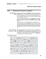
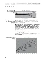
contains four identical blocks of circuitry coded as FLTR 1, 2 ,
3 and 4. One such block is shown below (
See figure 20.1
).
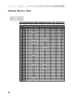
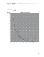
This filter block contains section A, a 1st order low pass filter, and section B, a
fully parametric equaliser. These two sections can be used to configure any
form of cut or boost Bell response or LF/HF shelving response, as indicated in
Figure 20.2
overleaf.
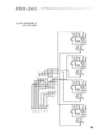
As it is unlikely that all four bands of the system will require equalisation,
spare sections can be used in series to increase the complexity for a particular
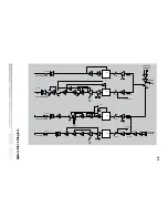
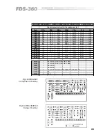
band. Reference to the attached full circuit diagram and the component
overlay of
Figure 20.3
will show the various interconnection methods
designed to interface these filter blocks into the correct crossover frequency
band.
20.3 Circuit
Description
Equalisation Options
Содержание FDS 360
Страница 1: ...1 FDS 360 User Manual...
Страница 51: ...51 User Notes...
Страница 52: ...52 User Notes...
Страница 53: ...53...
Страница 54: ...54 User Notes...

