background image

2 4

16.0

Phase Adjustment

One of the characteristics of the Linkwitz-Riley filter response is that at the
'corner' frequency between two adjacent bands the phase of the signal from
each band is the same. i.e. the two output signals are in phase. (Some small
departure from this occurs in band-pass outputs due to residual effects from the
opposite 'corner' frequencies).

In order to assist in obtaining accurate acoustical summation of the signals
from adjacent speaker units in a loudspeaker system, it is desirable to be able
to adjust the phase of the signal from one frequency band to that from the next
frequency band to properly allow for any phase errors that occur in the actual
loudspeakers and cabinets themselves. The three 'phase' controls on the 

FDS-

360

 are provided for this purpose.

It will be noticed that a small arrow associated with the graphics around this
phase control indicates which frequency band is being moved 'with' reference
to the other adjacent band, and that band four having no such control operates
as the starting reference.

In operation, phase alignment should commence at the highest frequency
band being used, and all other bands then adjusted in sequence down from
this band. Owing to residual effects as mentioned above, if after initial
adjustment some further re-adjustment is done on any band, then the lower
bands will need re-adjusting to compensate.

The polarity switch associated with each band can also be used to provide
further control range. If having rotated the phase control fully clockwise,
phase alignment is not achieved, then the polarity switch can be operated.
Returning the phase control to zero will then give the previous setting,
allowing a further 180 degrees of control. It should be remembered that this
phase adjustment is designed to assist in obtaining correct phase alignment
around the crossover frequencies of the speaker system, and is not the
equivalent of inserting digital delays into the frequency band. Should this be
required, then you should 

refer to section 13.0

 of the manual.

To assist in setting up the phase controls, a number of methods can be tried:

 Using pink noise and a spectrum analyser will provide a pictorial view of

the acoustical energy around the crossover regions, and operation of the phase
controls should be made to give the flattest response.

 Careful listening test to the speaker system whilst operating the phase

controls will provide another method of alignment.

 Applying a sinewave signal at a frequency equal to each crossover point in

turn, through the speaker system will allow operation of the phase control to
achieve a minimum speaker level. i.e. a cancellation. Pressing the polarity
switch will then invert one of the outputs to achieve a true summation.

Phase Adjustment

Содержание FDS 360

Страница 1: ...1 FDS 360 User Manual...

Страница 2: ...via a capacitor to prevent ground loops whilst ensuring good EMC compatibility V3 0 JMK 14 October 1996 We have written this manual with the aim of helping installers sound engineers and consultants...

Страница 3: ...0 Output Connections 14 10 1 XLR Plugs 14 11 0 Controls 16 11 1 Mode Switch 16 11 2 Level Control 16 11 3 Mute Switch 16 11 4 Polarity Switch 17 11 5 Mono Low Switch 17 11 6 Phase Control 17 11 7 Lim...

Страница 4: ...y Tables 27 18 1 Standard Filters 27 18 2 Full Range Frequency Card 27 19 0 BSS Supported Options 30 19 1 Output Balancing 30 19 2 Security Cover 30 20 0 FDS 360 Equalisation Options 31 20 1 Introduct...

Страница 5: ...e units work best when they are driven over a limited band of frequencies for example Low Mid and High Any crossover aims to provide the division of the audio band necessary so each drive unit receive...

Страница 6: ...tive crossover does the same job as a passive crossover but with more precision flexibility efficiency and quality Fig 2 1 Active and Passive Crossovers Crossover frequencies can be more readily alter...

Страница 7: ...opes in excess of 12dB OCT are rarely achieved and power rolloff is 4 times less rapid per octave Fig 3 1 Crossover Terminology If one frequency range is driven into clip drive units and horns in othe...

Страница 8: ...of frequencies around the crossover point this is where the units from two adjacent frequency ranges are contributing near equal amounts of sound pressure More predictable sound dispersion By providi...

Страница 9: ...kwitz Riley responses are supplied as standard Internal equalisation option Every FDS 360 is manufactured to the highest professional standards with a robust steel case high quality circuit boards and...

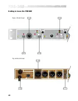
Страница 10: ...10 Getting to know the FDS 360 11 2 11 4 11 5 11 8 Fig 6 1 Front Panel Fig 6 2 Rear Panel FUSE 5x20mm 2 4 0 5 1 ON OFF WA 5 1 ON OFF WA 10 0 8 0 11 1...

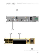
Страница 11: ...11 11 3 11 6 All numbers in bubbles refer to Section numbers 5 1 2 4 8dB ON OFF WATS560B 4H 5 1 2 4 8dB ON OFF WATS560B 4H 5 1 2 4 8dB ON OFF WATS560B 4H 5 1 2 4 8dB ON OFF WATS560B 4H 11 7 13 0 9 0...

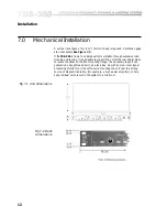
Страница 12: ...rt the unit at the rear and or sides to lessen the stress on the front mounting flange The necessary support can generally be bought ready built as a rack tray As with any low level signal processing...

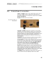
Страница 13: ...lity plug attached to the free end to facilitate the correct and proper connections AC Power Fusing The incoming line power passes through a 200mA for 240V only anti surge T fuse accessible from the r...

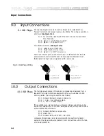
Страница 14: ...nd or signal 0V at the source end 9 1 XLR Plugs Fig 9 1 XLR Plug Wiring 10 0 Output Connections 10 1 XLR Plugs The four signal outputs are DC blocked low impedance unbalanced from a standard 3 pin mal...

Страница 15: ...th a traditional transformer balanced output either output phase or hot or cold can be linked to ground to unbalance the line without upsetting the operation of the unit As with a transformer output l...

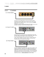
Страница 16: ...trol The four front panel controls adjust the level of the program in each of the frequency bands and is set to give a precise restricted range of 6dB In their fully anticlockwise position they do not...

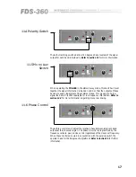
Страница 17: ...t stereo image This gives a mono low signal feed which is often desirable for low frequency information Refer to section 14 3 for more information regarding mono low linking 11 6 Phase Control These t...

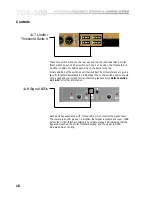
Страница 18: ...of the switches will then subtract from this reference to give a specific threshold adjustable in 0 5dB steps The centre switch position should not be used and is provided for manufacturing reasons on...

Страница 19: ...pport The card located in position FC1 is for the first break point that in position FC2 is for the second break point and that in position FC3 is for the third break point Card Location for Four Way...

Страница 20: ...up in the mute mode thus maintaining protection but after approximately 20 seconds will automatically un mute itself to allow full operation to commence 13 2 Auto Mute Cancel As mentioned in section 1...

Страница 21: ...moved and replaced by linking CHN 2 SEND and BAND 1 IN The same wire link can be used and inspection will show that the link is just rotated around the BAND 1 IN position As standard the FDS 360 has a...

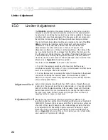
Страница 22: ...hat the power amplifiers are capable of providing This will protect speaker units that have a lower power rating than that of the amplifier To allow the maximum power amplifier output to be applied to...

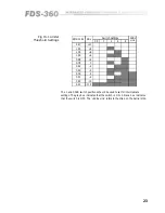
Страница 23: ...0 5 1 2 4 8 10 8 6 4 2 0 2 4 6 8 10 11 5 Fig 15 1 Limiter Threshold Settings The 1 and 0 5dB switch positions should be used to set for intermediate settings The grey box indicates that the switch is...

Страница 24: ...further re adjustment is done on any band then the lower bands will need re adjusting to compensate The polarity switch associated with each band can also be used to provide further control range If h...

Страница 25: ...ilter sections which avoids the frequency shift effect when limiting occurs The dynamic time constants are set by capacitor C10 on the frequency card The phase control linearity is set by capacitor C9...

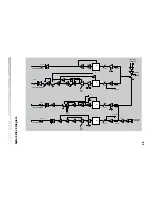
Страница 26: ...V E L P O L 3 0 F 1 F 1 M U T E I N S E R T L E V E L P O L F 2 2 w M U T E F 2 F 1 2 w F 1 2 w 2 w 2 w 2 w C H A N N E L 2 O U T P U T I N S E R T L E V E L M O N O T I E F 3 M U T E F 3 F 2 F 2 3 0...

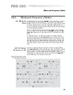
Страница 27: ...tors should be 5 tolerance or better Figure 18 1 shows how these components relate to the separate filter blocks to assist in making mixed frequency cards that might be needed for speaker systems that...

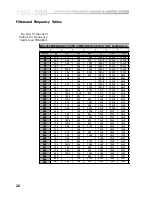
Страница 28: ...15k 150k 27k 33nF 100nF 47nF 280 13k 180k 43k 56k 33nF 100nF 47nF 300 15k 47k 27k 150k 33nF 100nF 47nF 350 15k 27k 39k 39k 33nF 100nF 47nF 400 10k 56k 18k 330k 33nF 100nF 47nF 500 6k8 15k 150k 33nF 47...

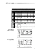
Страница 29: ...k 8k2 100k 3n3F 6n8F 2n2F 9k5 15k 56k 82k 33k 1n0F 6n8F 2n2F 10k0 15k 47k 43k 47k 1n0F 6n8F 2n2F 12k0 12k 43k 27k 62k 1n0F 6n8F 2n2F 15k0 7k5 15k 1n0F 6n8F 2n2F 18k0 6k2 15k 82k 1n0F 6n8F 1n0F 20k0 5k...

Страница 30: ...as part of the case structure of the FDS 360 so provision has been made for the AR204 to be either rack mounted or a 1U front panel which has the capacity to mount 2 x AR204 or to be individually moun...

Страница 31: ...rom the FDS 360 2 Fit the two support pillars onto the main circuit board using the screws and washers provided Replace the bottom cover 3 Carefully cut and remove the four resistors located in positi...

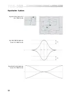
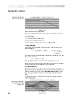
Страница 32: ...32 Fig 20 1 Schematic for one filter block Fig 20 2 Bell Response curve for filter block Fig 20 3 HF LF Response curve for filter block Equalisation Options...

Страница 33: ...ld be taken that R2 is factory fitter as 10k ohms Inspection of the circuit will show that it is also possible to change the gain of the filter block at this point The actual gain in dB is G dB 20 x l...

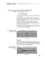
Страница 34: ...Fc 1 6 28 x Rf x Cf Such that for Rfa Rfb 10k and Cfa Cfb 16nF than Fc 1kHz Design limits for Rf should be within the range 2k to 100k ohms There are no limits for Cf apart from physical space on the...

Страница 35: ...tor is fitted in the cut of C position on the circuit board Notch depths of up to 50dB can be achieved however this depends on the close matching of the frequency determining components An example of...

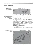
Страница 36: ...s correction curve is the desired response of the FDS 360 equalisation section From this correction curve the amount of dB boost or cut and the centre frequency Fc are easily obtained by inspection Th...

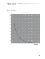
Страница 37: ...g 20 10 Design Curves for RdB 0 1 2 3 4 5 6 7 8 9 10 11 12 13 14 15 16 17 20 40 60 80 100 120 140 160 180 200 220 240 260 280 300 320 340 360 380 400 R Boost Cut k dB Boost Cut R Boost Cut vs dB Boost...

Страница 38: ...he outputs of the filter blocks O P Are the band insert returns and are connected to the Filter O P SOURCE Are the band insert sends and are connected to the Filter I P Note that the main CHN1 and CHN...

Страница 39: ...9 S O A C U T B O O S T 2 3 1 1 6 7 R 3 3 1 0 K R 3 5 1 0 K R 3 6 4 7 K R 3 8 S O A I C 6 3 5 3 C 8 S O A R 2 8 S O A R 3 0 2 K 2 R 2 5 S O A R 2 4 4 7 K I C 1 C 6 S O A R 1 6 S O A R 1 5 4 7 K R 1 4...

Страница 40: ...r and X2 X4 is a resistor If the 4 7K resistor is changed there may be some interaction between boost resistors R23 R34 to R28 R39 See figure 20 13 for boost resistor values If this occurs the values...

Страница 41: ...A R 1 8 4 K 7 R 2 1 2 K 2 R 2 0 1 0 K R 1 9 S O A R 2 2 S O A C 5 S O A I C 3 3 5 3 7 R 1 5 4 7 K R 1 6 S O A C 6 S O A I C 3 3 5 3 F L T R 2 R 6 6 5 7 1 6 7 R 2 1 0 K R 1 1 0 K C 1 S O A R 1 4 4 7 K...

Страница 42: ...tage peaks in excess of their maximum rating Should the FDS 360 be inadvertently connected to 3 phase line line voltages or to 240V when selected to 120V or any other incorrect voltage these suppresso...

Страница 43: ...ctions on your input and output plugs See sections 9 0 10 0 Unshielded cables improperly wired connectors and damaged cables are the most common cause of sound system hums and buzzes Then refer to sec...

Страница 44: ...n system interconnections Compressor An electronic circuit which reduces its input to output gain as the input signal increases above a predetermined threshold level dB A unit for expressing the ratio...

Страница 45: ...ormal operating level that can be used before serious distortion commences Headroom Impedance The AC equivalent of resistance and measured in ohms It indicates the amount of drive required for an inpu...

Страница 46: ...asts for a small period of time relative to the rest of the signal The level of a transient can often reach 10 times or so the normal operating level of the audio equipment and may cause distortion Tr...

Страница 47: ...z 18dB OCT 26kHz ultrasonic Outputs Unbalanced 50 milli ohm current limited source to drive 600 ohm load Maximum level 20dBm Limiter Separate for each band with attack and release times scaled to suit...

Страница 48: ...epaid You should include a statement listing the faults found The unit s serial number must be quoted in all correspondence relating to a claim We recommend that you record your purchase information h...

Страница 49: ...Controls Limiter Adjustment 22 Limiter Cancel See Rear Barrier Strip Limiter Threshold Reference See Rear Barrier Strip Limiter Threshold Switch See Con trols Limiters 22 Linkwitz Riley 8 M Mains Conn...

Страница 50: ...50 Index V Voltage See Mains Connection W Warranty 48 Wiring convention See Inputs WWW address 48 Z Zero Phase difference 8...

Страница 51: ...51 User Notes...

Страница 52: ...52 User Notes...

Страница 53: ...53...

Страница 54: ...54 User Notes...

Отзывы: