25
System Diagram/Description
17.0
System Diagrams and Descriptions
The input section of the
FDS-360
contains the input signal de-balancing,
subsonic and ultrasonic filtering. From here the signal is fed into four parallel
paths for filtering and limiting. These four paths are essentially similar, apart
from the number and types of filters required. The input for channel 2 is fed
via the mode switch.
The gain reduction circuitry for the limiters is located after the level controls
and before the main crossover filters, and is of the feedback type. The main
crossover filters consists of two series second order filter blocks configured to
achieve the Linkwitz-Riley response. By utilising separate order filters in this
manner, it is possible to have 12, 18 or 24dB/OCT responses with the low and
high pass filters having either the same or differing cutoff frequencies. This
flexibility is achieved by suitable programming of the plug-in frequency cards.
The DC control voltage for the limiter circuits is derived from a point between
the two series filter sections which avoids the frequency-shift effect when
limiting occurs. The dynamic time constants are set by capacitor C10 on the
frequency card. The phase control linearity is set by capacitor C9 on the
frequency card. The final output stages driving the MUTE relays utilise
discrete output transistors to ensure adequate current drive into long lengths of
signal cable. The MUTE relays are controlled by the front panel mute switch,
the power-up auto mute routine, the auto mute cancel facility, and the
circuitry which monitors the power supply circuits. If for any reason the
internal power supplies fail, all mute relays operate to protect the output from
any DC output levels.
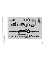
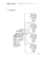
See next page
for a full system block diagram.
17.1 Full unit
As mentioned in section 14.0, the cutoff frequency of the subsonic input filter
is set as standard at 30Hz. For sub-woofer speaker systems, it may be
desirable to change this down to 15Hz. Should this be required, the following
table details the extra capacitors that should be fitted into the appropriately
marked space on the main circuit board of the unit.
Channel 1: C2, C4, C24A, C23A, C27A as 220nF 5% C28A as 470nF 5%
Channel 2: C14, C15, C34A, C35A, C36A as 220nF 5% C73A as 470nF 5%
17.2 15Hz Subsonic
Filter Change
Содержание FDS 360
Страница 1: ...1 FDS 360 User Manual...
Страница 51: ...51 User Notes...
Страница 52: ...52 User Notes...
Страница 53: ...53...
Страница 54: ...54 User Notes...

