background image


8.2 

Cut down installation plate installation 


8.2.1 


Reduced installation plate.


8.2.2 

The installation plate is recommended to be supplied ‘factory cut. All four sides can be supplied cut down 

         where required. 

8.2.3 

A length of steel supporting angle should be affixed to the top of the opening as shown in fig.  5 

8.2.4 

The damper should be installed within and affixed to the top supporting angle. 

8.2.5 

Fire batt material should be cut to suit void with zero clearance to produce an interference fit. The 
installation  


plate face, and all edges should be ‘glued’ in place, and a bead of intumescent mastic applied at all joints.  

8.2.6 

Note 

– two layers of 50mm min thickness are required to comply with the ‘as tested’ installation method. 

8.2.7 

Screw-in 50mm long spiral (pig tail) fixings through installation plate into batt material utilising one of the pair   

                        of corner holes, and all intermediate fixing holes. (It may be necessary to drill additional fixing holes  
                        depending on plate size reduction). 

8.2.8 

Recommended minimum void gap (per side) is 40mm and maximum 600mm. 


8.3 

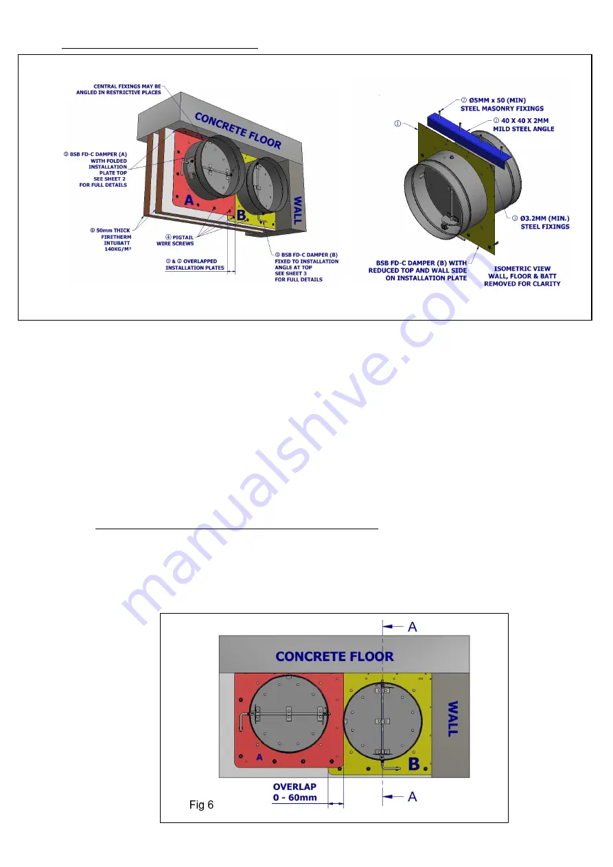
Overlapping installation plate installation (refer to fig 6) 

8.3.1 

It is permissible to overlap the installation plate with another installation plate where two dampers  are near to 
each other. 

8.3.2 

The two overlapping plates should be secured together by drilling 3.2mm dia holes and using  steel rivets 
mirroring the existing fixing pitches. 

8.3.3     

Screw-in 50mm long spiral (pig tail) fixings through installation plate perimeter into batt material  utilising one of 

the pair of corner holes, and all intermediate fixing holes 


Fig 5 

Содержание FD-C

Страница 1: ...e the structure is sufficiently supported to conform to design specification 3 4 Dry wall openings must be lined Please see figure 1 3 5 Ensure that appropriate fire rated plasterboard is used through...

Страница 2: ...Control Officer and or specifying authority 5 10 The installation method contained herein assumes the wall has been built prior to the damper opening preparation Optionally the opening may already be...

Страница 3: ...vet tails on the back of the installation plate A shallow provision to be made as appropriate 7 2 Preferably prepare aperture whilst building wall floor or cut aperture if wall floor already exists 7...

Страница 4: ...e to produce an interference fit The installation plate face and all edges should be glued in place and a bead of intumescent mastic applied at all joints 8 1 4 Note two layers of 50mm min thickness a...

Страница 5: ...he as tested installation method 8 2 7 Screw in 50mm long spiral pig tail fixings through installation plate into batt material utilising one of the pair of corner holes and all intermediate fixing ho...

Страница 6: ...hen required 9 3 The cleats can be easily bent out at right angles by hand using a medium size flat head screwdriver at one of the cleats pressed out corners to start see figure 7 9 4 The cleats can b...

Страница 7: ...dertaken annually Local regulations conditions may override this with periodic Inspection being carried out more frequently where corrosive or dirty conditions prevail The maintenance log should be re...

Страница 8: ...l pliable Damper not in expected normal state Fusible link FL missing Fit Fusible Link FL Part No 201448 Fusible link FL not tightened properly Tighten Fusible Link FL Fusible Link FL has activated Me...

Страница 9: ...LL OPEN FINAL INSPECTION BY Print name Signature Company Date This document is available for free download from the BSB website This document is subject to change without notice BSB Engineering Servic...

Отзывы: