background image

5

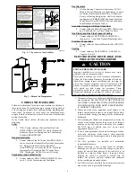
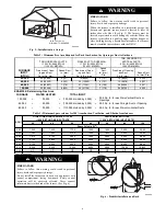
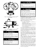
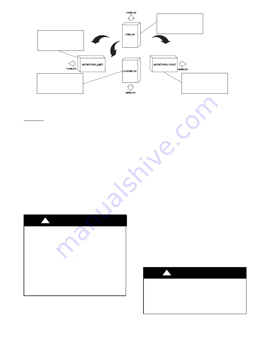
THE BLOWER IS LOCATED

TO THE RIGHT OF THE

BURNER SECTION, AND

AIR CONDITIONED AIR IS

DISCHARGED TO THE LEFT.

THE BLOWER IS

LOCATED BELOW THE

BURNER SECTION, AND

CONDITIONED AIR IS

DISCHARGED UPWARD.

THE BLOWER IS

LOCATED ABOVE THE

BURNER SECTION, AND

CONDITIONED AIR IS

DISCHARGED DOWNWARD

THE BLOWER IS

LOCATED TO THE LEFT

OF THE BURNER SECTION,

AND CONDITIONED AIR IS

DISCHARGED TO THE RIGHT.

A02097

Fig. 4 -- Multipoise Orientations

LOCATION

GENERAL

This multipoise furnace is shipped in packaged configuration.

Some assembly and modifications are required when used in any
of the four applications shown in Fig. 4.
This furnace must:

S

be installed so the electrical components are protected
from water.

S

not be installed directly on any combustible material
other than wood flooring for upflow applications.

Downflow installations require use of a factory--ap-
proved floor base or coil assembly when installed on

combustible materials or wood flooring (refer to SAFE-
TY CONSIDERATIONS).

S

be located close to the chimney or vent and attached to
an air distribution system. Refer to Air Ducts section.

S

be provided ample space for servicing and cleaning.
Always comply with minimum fire protection clear-

ances shown on the furnace clearance to combustible
label.

CARBON MONOXIDE POISONING HAZARD

Failure to follow this warning could result in personal

injury or death, and unit component damage.
Corrosive or contaminated air may cause failure of parts

containing flue gas, which could leak into the living space.

Air for combustion must not be contaminated by halogen

compounds, which include fluoride, chloride, bromide, and

iodide. These elements can corrode heat exchangers and

shorten furnace life. Air contaminants are found in aerosol

sprays, detergents, bleaches, cleaning solvents, salts, air

fresheners, and other household products. Do not install

furnace in a corrosive or contaminated atmosphere. Make

sure all combustion and circulating air requirements are met,

in addition to all local codes and ordinances.

!

WARNING

The following types of furnace installations may require
OUTDOOR AIR for combustion due to chemical exposures:

S

Commercial buildings

S

Buildings with indoor pools

S

Laundry rooms

S

Hobby or craft rooms, and

S

Chemical storage areas

If air is exposed to the following substances, it should not be used

for combustion air, and outdoor air may be required for

combustion:

S

Permanent wave solutions

S

Chlorinated waxes and cleaners

S

Chlorine based swimming pool chemicals

S

Water softening chemicals

S

De--icing salts or chemicals

S

Carbon tetrachloride

S

Halogen type refrigerants

S

Cleaning solvents (such as perchloroethylene)

S

Printing inks, paint removers, varnishes, etc.

S

Hydrochloric acid

S

Cements and glues

S

Antistatic fabric softeners for clothes dryers

S

Masonry acid washing materials

All fuel--burning equipment must be supplied with air for fuel
combustion. Sufficient air must be provided to avoid negative

pressure in the equipment room or space. A positive seal must be
made between the furnace cabinet and the return--air duct to

prevent pulling air from the burner area and from draft safeguard

opening.

PERSONAL

INJURY

AND/OR

PROPERTY

DAMAGE

Improper use or installation of this furnace may cause

premature furnace component failure.
This furnace is not permitted to be used for heating of

buildings under construction.

CAUTION

!

Содержание 830CA

Страница 1: ...REQUIREMENTS 23 SIDEWALL VENTING 23 START UP ADJUSTMENT AND SAFETY CHECK 25 GENERAL 25 START UP PROCEDURES 25 ADJUSTMENTS 25 FURNACE SETUP SWITCHES 26 AIR DELIVERY CFM 30 COOLING OR CONTINUOUS AIRFLO...

Страница 2: ...ir for Combustion and Ventilation section 4 Combustion products must be discharged outdoors Connect this furnace to an approved vent system only as specified in the Venting section of these instructio...

Страница 3: ...M VENT CONNECTION IN MM SIZE SHIP WT LB KG ACCESSORY FILTER MEDIA CABINET SIZE IN MM 36040C17 17 1 2 445 15 7 8 403 11 9 16 294 16 406 4 102 119 54 16 406 48060C17 17 1 2 445 15 7 8 403 11 9 16 294 16...

Страница 4: ...Z223 1 Chapters 12 and 13 ELECTROSTATIC DISCHARGE ESD PRECAUTIONS PROCEDURE FURNACE RELIABILITY HAZARD Improper installation or service of furnace may cause premature furnace component failure Electro...

Страница 5: ...include fluoride chloride bromide and iodide These elements can corrode heat exchangers and shorten furnace life Air contaminants are found in aerosol sprays detergents bleaches cleaning solvents sal...

Страница 6: ...40 25807 7 178 27 17391 6 152 20 12904 5 127 100 000 50 32258 8 203 34 21739 7 178 25 16130 6 152 EXAMPLE Determining Free Area FURNACE WATER HEATER TOTAL INPUT 100 000 30 000 130 000 divided by 4 000...

Страница 7: ...NFILTRATION METHOD Outdoor Combustion Air Method 1 Provide the space with sufficient air for proper combustion ventilation and dilution of flue gases using permanent horizontal or vertical duct s or o...

Страница 8: ...ements apply to the Standard Method and to the Known Air Infiltration Rate Method 1 Adjoining rooms can be considered part of a space if a There are no closeable doors between rooms b Combining spaces...

Страница 9: ...leveling legs 1 Position furnace on its back Locate and drill a hole in each bottom corner of furnace See Fig 10 2 For each leg install nut on bolt and then install bolt and nut in hole Install flat...

Страница 10: ...nd RH side The furnace can be hung from floor joists rafters or trusses or installed on a non combustible platform blocks bricks or pad Table 4 Opening Dimensions In mm FURNACE CASING WIDTH APPLICATIO...

Страница 11: ...r rack for assembly and installation options AIR DUCTS General Requirements The duct system should be designed and sized according to accepted national standards such as those published by Air Conditi...

Страница 12: ...r other accessories All accessories MUST be connected to duct external to furnace casing A190346 Fig 14 Duct Flanges 1 4 6mm THREADED ROD 4 REQ SECURE ANGLE IRON TO BOTTOM OF FURNACE WITH 3 8 x3 4 19m...

Страница 13: ...NOT cut into casing sides left or right Side opening is permitted for only upflow and most horizontal furnaces See Fig 19 Bypass humidifier connections should be made at ductwork or coil casing sides...

Страница 14: ...hen flexible connectors are used the maximum length shall not exceed 36 inches 915 mm 3 When lever handle type manual equipment shutoff valves are used they shall be T handle valves 4 The use of coppe...

Страница 15: ...nit Amps Unit Ampacity Minimum Wire Size AWG Maximum Wire Length ft Maximum Fuse or CKT BKR Amps Maximum Minimum 036040 115 60 1 127 104 11 4 12 6 14 29 15 048060 115 60 1 127 104 11 4 12 6 14 29 15 0...

Страница 16: ...ithin furnace away from sharp edges rotating parts and hot surfaces ELECTRICAL CONNECTION TO J BOX Electrical Box on Furnace Casing Side FIRE OR ELECTRICAL SHOCK HAZARD Failure to follow this warning...

Страница 17: ...1 4 in female quick connect terminals to the two male 1 4 in quick connect terminals on the control board marked EAC 1 and EAC 2 The terminals are rated for 115VAC 1 0 amps maximum and are energized d...

Страница 18: ...CTORY 115 VOLT WIRING Connect Y Y2 terminal as shown for proper operation Some thermostats require a C terminal connection as shown If any of the original wire as supplied must be replaced use same ty...

Страница 19: ...sition for heat pump installations 7 Dip switch No 2 on Thermidistat should be set in OFF position for single speed compressor operation This is factory default 8 Dip switch No 2 on Thermidistat shoul...

Страница 20: ...local building codes and furnace and vent manufacturers instructions These furnaces are design certified as Category I furnaces in accordance with current edition of ANSI Z21 47 CSA 2 3 and operate w...

Страница 21: ...CHIMNEY IN2 MM2 12 7741 19 12258 28 18064 38 24516 6 1 8 74 119 178 257 8 2 4 80 130 193 279 10 3 0 84 138 207 299 15 4 5 NR 152 233 334 20 6 0 NR NR 250 368 30 9 1 NR NR NR 404 APPLIANCE APPLICATION...

Страница 22: ...22 A180242 Fig 31 Chimney Inspection Chart...

Страница 23: ...termine the correct location of the knockout to be re moved 4 Use a hammer and screwdriver to strike a sharp blow be tween the tie points and work the slug back and forth until the slug breaks free CU...

Страница 24: ...ove 3 Side outlet vent for upflow and downflow installations must use Type B vent immediately after exiting the furnace except when factory authorized Downflow Vent Guard Kit is used in the downflow p...

Страница 25: ...not operate if any thermostat signal is present at the control Refer to service label attached to furnace or See Fig 38 Component test sequence is as follows a Inducer motor turns on at 50 duty cycle...

Страница 26: ...26 Table 10 Furnace Setup Switch Description A190351...

Страница 27: ...27 A190348 Fig 38 Service Label...

Страница 28: ...p NOTE If orifice hole appears damaged or it is suspected to have been redrilled check orifice hole with a numbered drill bit of correct size Never redrill an orifice A burr free and properly sized or...

Страница 29: ...onnect an amp meter as shown in Fig 41 across the R and W subbase terminals or R and W wires at wall R Y W G 10 TURNS THERMOSTAT SUBBASE TERMINALS WITH THERMOSTAT REMOVED ANITICIPATOR CLOCK ETC MUST B...

Страница 30: ...5 1565 1525 1490 1455 1415 1375 1335 1295 CF Switches SW3 3 SW3 2 SW3 1 Cont Fan Default OFF OFF OFF 530 545 545 535 505 495 485 See Note 4 Continuous Fan Airflow SW3 OFF OFF ON 530 545 545 535 505 49...

Страница 31: ...F OFF OFF 1785 1800 1805 1830 1830 1845 1855 1860 1850 1840 Cooling Airflow SW2 Low Cooling Airflow SW3 OFF OFF ON 635 630 See Note 4 OFF ON OFF 785 820 865 See Note 4 OFF ON ON 1040 1045 1070 1085 11...

Страница 32: ...n furnace wiring diagram Fig 42 Cooling A C or Continuous Fan Airflow Selection Chart Check Safety Controls 1 Check Main Limit Switch es This control shuts off combustion control system and en ergizes...

Страница 33: ...6 94 38 76 192 38 95 189 474 96 38 75 188 39 92 185 462 98 37 74 184 40 90 180 450 100 36 72 180 41 88 176 439 102 35 71 178 42 86 172 429 104 35 69 173 43 84 167 419 106 34 68 170 44 82 164 409 108 3...

Страница 34: ...8 1 8 1 9 2 0 1646 925 1 8 1 8 1 8 1 9 950 1 8 1 8 1 8 1 8 975 1 8 1 8 1 8 1 8 1000 1 8 1 8 1 8 1 8 Table 16 Gas Valve Outlet Pressure for Gas Heat Values at Altitude 80 000 Tabulated Data Based on 8...

Страница 35: ...TH HAZARD Failure to follow this warning could result in personal injury death and or property damage The ability to properly perform maintenance on this equipment requires certain knowledge mechanica...

Страница 36: ...stall blower access door and replace outer door or refer to the SERVICE label on the front of the blower access door for more informa tion Component Self Test Component Test can ONLY be initiated by p...

Страница 37: ...ving filter access door 2 Remove filter cabinet door 3 Slide filter out of cabinet 4 If equipped with permanent washable 3 4 in 19 mm fil ter clean filter by spraying cold tap water through filter in...

Страница 38: ...n outdoor circuit breaker on after completing cooling cycle FLAME SENSOR CLEANING AND SERVICING IGNITOR Cleaning Flame Sensor The following items must be performed by a qualified service technician If...

Страница 39: ...as follows NOTE The materials needed in item 9 can usually be purchased at local hardware stores a Remove metal screw fitting from wire brush to allow in sertion into cable b Insert the twisted wire...

Страница 40: ...od If the transducer fails to reach target pressure the inducer motor IDM will remain running until tar get pressure is maintained After the transducer maintains pressure target the furnace control CP...

Страница 41: ...he blower motor BLWM is operating When the thermostat is satisfied the R to G and Y circuit are opened The outdoor unit stops and the furnace blower BLWM and electronic air cleaner terminal EAC 1 will...

Страница 42: ...cedure enough you will eventually shift the continuous blower airflow to the lowest CF selection as shown in Fig 42 The selection can be changed as many times as desired and is stored in the memory to...

Страница 43: ...43 A190249 Fig 45 Wiring Diagram...

Страница 44: ...gs for dealer listing by brand name or contact BRYANT HEATING COOLING SYSTEMS Consumer Relations Department P O Box 4952 Syracuse New York 13221 4952 1 800 428 4326 Have available the model number ser...

Отзывы: