44
PARTS REPLACEMENT INFORMATION GUIDE
CASING GROUP
Outer door
Blower door
Top filler plate
Bottom filler plate
Bottom enclosure
ELECTRICAL GROUP
Control bracket
Junction box
Limit switch(es)
Circuit board
Door switch
Transformer
Wiring harness 115v
Wiring harness 24v
BLOWER GROUP
Blower housing
Blower cutoff
Blower motor
Blower wheel
Grommet
Power choke (where used)
Auxiliary limit switches
GAS CONTROL GROUP
Burner assembly
Orifice
Flame sensor
Hot surface ignitor
Gas valve
Manual reset limit switches
Burner support assembly
HEAT EXCHANGER GROUP
Heat exchanger cell
Cell panel
INDUCER GROUP
Housing assembly
Transducer
Inducer motor
Inducer wheel
Vent elbow assembly
TO OBTAIN INFORMATION ON PARTS:
Consult your installing dealer or classified section of your local telephone directory under
“Heating Equipment” or “Air Conditioning Contractors and Systems” headings for dealer listing by brand name or contact:
BRYANT HEATING & COOLING SYSTEMS
Consumer Relations Department
P.O. Box 4952
Syracuse, New York 13221--4952
1--800--428--4326
Have available the model number, series number, and serial number located on the unit rating plate to ensure correct replacement part.
Example of Model Number
MODEL
COOLING SIZE
(AIRFLOW)
HEATING SIZE
MOTOR
WIDTH
VARIATION
830CA
48
060
C
17
A
Training
My Learning Center is your central location for professional residential HVAC training resources that help strengthen careers
and businesses. We believe in providing high quality learning experiences both online and in the classroom.
Access My Learning Center with your HVACpartners credentials at
www.MLCtraining.com
. Please contact us at
with questions
.
Manufacturer reserves the right to discontinue, or change at any time, specifications or designs without notice and without incurring obligations.
E
2019 Bryant Heating & Cooling Systems 7310 W. Morris St. Indianapolis, IN 46231
Edition Date: 11/19
Replaces: II830CA--- 01
Catalog No. II830CA---02
Содержание 830CA
Страница 22: ...22 A180242 Fig 31 Chimney Inspection Chart...
Страница 26: ...26 Table 10 Furnace Setup Switch Description A190351...
Страница 27: ...27 A190348 Fig 38 Service Label...
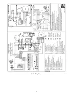
Страница 43: ...43 A190249 Fig 45 Wiring Diagram...

