3
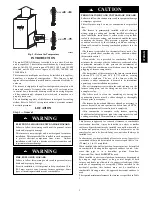
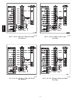
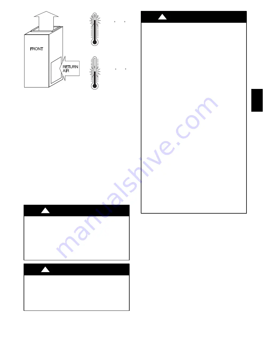
MAX 80 F / 27 C
MIN 55 F / 13 C
A06622
Fig. 3 -- Return Air Temperature
INTRODUCTION
The model 374RAN Furnace is available in two sizes. Each size
unit is capable of 3 heat/airflow combinations by a simple nozzle
change. Unit 036105 covers inputs of 70,000, 91,000, and 105,000
Btu, and unit 060120 covers inputs of 119,000, 140,000, and
154,000 Btuh.
This furnace is a multipoise unit. It may be installed in the upflow,
downflow, or horizontal configuration.
This furnace is
not
approved for installation in mobile homes, recreational vehicles, or
outdoors.
The furnace is shipped in the upflow configuration, complete with
burner and controls. It requires a line voltage (115 vac) connection
to control box, a thermostat hook--up as shown on wiring diagram,
oil line connection(s), adequate duct work, and connection to a
properly sized vent.
The air handling capacity of this furnace is designed for cooling
airflow. Refer to Table 13 for expected airflows at various external
duct static pressures.
LOCATION
Step 1 — General
ELECTRICAL SHOCK OR UNIT DAMAGE HAZARD
Failure to follow this warning could result in personal injury,
death and/or property damage.
This furnace is not watertight and is not designed for outdoor
installation. This furnace shall be installed in such a manner as
to protect electrical components from water.
Outdoor
installation would lead to a hazardous electrical condition and
to premature furnace damage.
!
WARNING
FIRE, EXPLOSION HAZARD
Failure to follow this warning could result in personal injury,
death and/or property damage.
For attic installation, it is important to keep insulation 12 in.
(305 mm) or more away from any furnace openings. Some
types of insulating materials may be combustibles.
!
WARNING
PERSONAL INJURY AND UNIT DAMAGE HAZARD
Failure to follow this caution may result in equipment damage
or improper operation.
This oil furnace may be used for construction heat provided
that:
--The furnace is permanently installed with all electrical
wiring, piping, venting and ducting installed according to
these installation instructions. A return air duct is provided,
sealed to the furnace casing, and terminated outside the space
containing the furnace. This prevents a negative pressure
condition as created by the circulating air blower, causing a
flame roll--out and/or drawing combustion products into the
structure.
--The furnace is controlled by a thermostat. It may not be “hot
wired” to provide heat continuously to the structure without
thermostatic control.
--Clean outside air is provided for combustion. This is to
minimize the corrosive effects of adhesives, sealers and other
construction materials. It also prevents the entrainment of
drywall dust into combustion air, which can cause fouling and
plugging of furnace components.
--The temperature of the return air to the furnace is maintained
between 55
_
F (13
_
C) and 80
_
F (27
_
C) with no evening
setback or shutdown. The use of the furnace while the
structure is under construction is deemed to be intermittent
operation per our installation instructions.
--The air temperature rise is within the rated rise range on the
furnace rating plate, and the firing rate has been set to the
nameplate value.
--The filters used to clean the circulating air during the
construction process must be either changed or thoroughly
cleaned prior to occupancy.
--The furnace, ductwork and filters are cleaned, as necessary, to
remove drywall dust and construction debris from all HVAC
system components after construction is completed.
--After construction is complete, verify furnace operating
conditions including ignition, input rate, temperature rise, and
venting, according to the manufacturer’s instructions.
CAUTION
!
This furnace is approved for reduced clearances to combustible
construction, therefore, it may be installed in a closet or similar
enclosure. Since this unit may be installed in an upflow, downflow,
or horizontal position, it may be located in a basement or on the
same level as area to be heated. In any case, unit should always be
installed level.
In a basement, or when installed on floor (as in a crawl space), it is
recommended that unit be installed on a concrete pad that is 1 in.
(25 mm) to 2 in. (51 mm) thick.
When installed in downflow position, furnace must not be installed
on combustible flooring unless approved subbase is used. Also,
since flue pipe is in a downflow position, Downflow
Conversion/Vent Guard Kit
MUST
be used.
When installed in a horizontal position, furnace may be suspended
by using an angle iron frame, as long as total weight of both
furnace and frame are allowed for in support calculations. (Other
methods of suspending are acceptable.) When installed in the
horizontal position, this furnace must not be installed on
combustible flooring unless the approved horizontal subbase is
used.
The required minimum clearances for furnace are specified in Table
1.
374RAN


