15
Oil Fired Heating Mode
1. The thermostat closes R to W.
2. Burner motor starts. The burner motor fan pre--purges the
combustion chamber and vent for 10 seconds, establishing
the combustion air pattern. During this time the solenoid
valve holding oil pressure will be approximately 100 psig.
Solenoid valve opens, allowing oil to flow through nozzle.
At the same time, the burner motor’s ignition coil produces
spark.
3. Spark ignites oil droplets.
4. Cad cell senses flame and burner continues to fire. Ignition
transformer ceases sparking.
5. After the “Pre--Run” ON--delay time, the circulating air
blower starts.
6. The circulating--air blower and burner motor remain ON
until the thermostat is satisfied. The solenoid valve remains
open (R40--F).
7. Thermostat is satisfied.
8. The solenoid valve closes and the burner fan motor shuts
down.
9. The furnace blower motor continues operating at 38 percent
of the heating airflow for an additional 3 min.
Cooling Mode
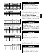
1. Single--Speed Cooling Outdoor Unit (See Fig. 15 for
thermostat connections.)
a. The thermostat closes R to G--and--Y circuits. The
R--Y/Y2 circuit starts outdoor unit, and R to G--and--
Y/Y2 circuits start the furnace BLWM on cooling speed.
b. When thermostat is satisfied, the R to G--and--Y/Y2
circuits are opened. The outdoor unit stops, and furnace
BLWM continues operating at 50% of the cooling
airflow for an additional 180 sec.
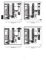
2. Two--Speed Cooling Outdoor Unit (See Fig. 16 for
thermostat connections.)
a. The thermostat closes the R to G--and--Y1 circuits for
low cooling or closes the R to G--and Y1--and--Y/Y2
circuits for high cooling. The R to Y1 circuit operates
the outdoor unit on low--cooling speed. The R to
G--and--Y1 circuit operates the furnace BLWM at
low--cooling airflow 55% of single--speed cooling
airflow. The R to Y1--and--Y2 circuits operate the
outdoor unit on high--cooling speed, and the R to
G--and--Y/Y2--and--Y1 circuits operate furnace BLWM
at high--cooling airflow.
NOTE
: Y1 is found in the furnace and in the outdoor unit. The
furnace control CPU controls BLWM airflow by sensing only
G--and--Y1 for low--cooling airflow and--and--Y1--and--Y/Y2--for
high--cooling airflow.
b. When the thermostat is satisfied, the R to G--and--Y1 or
R to G--and--Y1--andY/Y2 circuits open. The outdoor
unit stops, the furnace blower continues operating at
50% of the cooling airflow for an additional 3 min.
Continuous--Blower Mode
1. When R to G circuit is closed by the thermostat, BLWM
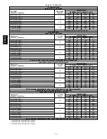
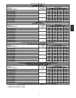
operates at 64%, 75%, or 86% of single--speed cooling
airflow; depending on dipswitch setting. (See Table 13 and
Fig. 19.)
2. During a call for heat, the BLWM will keep continuous
blower speed until the end of “Short run” delay period,
after which the BLWM operates at the appropriate oil heat-
ing airflow. The BLWM reverts to continuous blower air-
flow after the heating cycle is completed.
3. When thermostat “calls for low--cooling”, the BLWM keeps
continuous--blower speed until the end of “Short run” delay
period. After which the BLWM operates at the appropriate
low--cooling airflow. When the thermostat is satisfied, the
BLWM switches to continuous--blower airflow.
4. When the thermostat calls for high cooling, the BLWM
keeps continuous--blower speed until the end of “Short run”
delay period, after which the BLWM operates at the
appropriate high--cooling airflow.
5. When R--G circuit is opened, the BLWM stops immediately.
Heat Pump
NOTE
: A dual--fuel thermostat is required when variable--speed
furnaces are used with heat pumps. See dual--fuel thermostat
Installation Instructions for interface connections. The interface
prevents simultaneous operation of both furnace and heat pump,
and prevents direct transition from heat pump to furnace operation.
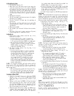
1. Single--Speed Heat Pump Cooling
(See Fig. 17 for
thermostat connections.)
a. The thermostats close the R to Y/Y2--and--G--and--O
circuits to operate the furnace BLWM at cooling airflow.
The Y/Y2 input to the furnace control is necessary to
provide adequate cooling airflow.
b. When thermostat is satisfied, furnace BLWM continues
operating at 50% of the cooling airflow for an
additional 3 min.
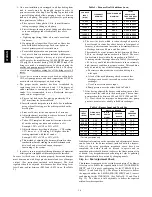
2. Two--Speed Heat Pump Cooling (See Fig. 18 for thermostat
connections.)
a. The thermostat closes the R to G--and--Y1--and--O
circuits to operate the furnace BLWM at low--cool
airflow. The thermostat R to
G--and--Y/Y2--and--Y1--and--O circuits operate the
furnace BLWM at high--cool airflow.
NOTE
: The furnace control CPU controls blower airflow by
sensing G, Y1, and O for low--cool airflow and G, Y1, Y/Y2, and
O for 2--speed high--cool airflow.
b. When the thermostat is satisfied, the furnace BLWM
continues operating at 50%of the additional 3 min.
3. Single--Speed Heat Pump Heating
(See Fig. 17 for
thermostat connections.)
a. The thermostats close R to G--and--Y/Y2 circuits to
operate the furnace BLWM at heat pump heating
airflow. Heating airflow is the same as cooling airflow.
b. When thermostat is satisfied, the furnace BLWM
continues operating at 50% of the heat pump heating
airflow for an additional 3 min.
4. Two--Speed Heat Pump Heating (See Fig. 18 for thermostat
connections.)
a. The thermostat closes the R to Y1--and--G circuits for
low heat and operates the furnace BLWM at heat pump
low--heat airflow. Closing R--Y/Y2, Y1 and G circuit to
furnace provides BLWM heat pump high--heat airflow.
NOTE
: The furnace control CPU controls BLWM airflow by
sensing G and Y1 for heat pump low--heat airflow, and G, Y1, and
Y/Y2 for heat pump high--heat airflow.
b. When the thermostat is satisfied, the furnace BLWM
continues operating at 50% heating airflow for an
additional 3 min.
c. Opening only R--Y/Y2 circuit switches BLWM to heat
pump low--heat airflow.
Defrost
When furnace controls R to W/W1--and--Y/Y2 circuits are closed,
furnace control CPU starts and burner and BLWM operation is at
oil--heating airflow during defrost.
Step 3 — Combustion Check
In order to obtain optimum performance from oil burner, the
following setup procedures must be followed:
374RAN


