13
Accessory Installation
1. General
When installing optional accessories to this appliance,
follow manufacturer’s Installation Instructions included
with accessory. Other than wiring for thermostat, wire with
a minimum of type ’T’ insulation (63
_
F/35
_
C rise) must be
used for accessories.
2. Auxiliary Terminals
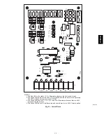
The HUM 120 VAC terminals on the electronic control
board are tied directly to the #8 pin of the 9 pin connector
and provide a 120 VAC signal whenever the burner is
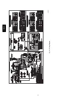
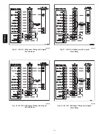
energized. (See Fig. 14.)
Supplementary 120 VAC and
neutral terminals can be used for accessory wiring. See
Electronic Air Cleaner and Humidifier sections for further
information.
3. Electronic Air Cleaner Connections
When using an electronic air cleaner with variable--speed
oil--fired furnaces, use an Airflow Sensor kit. As the air
cleaner is connected to constant 120 VAC power, the
airflow sensor turns on the electronic air cleaner when the
furnace blower is operating.
4. Humidifier/Humidistat Connections
To ensure humidifier will operate properly, use HUM
output of Humidistat Control to control humidifier
operation. A 24--VAC signal can be connected from the W
and C on terminal block connections on the electronic board
or a 120 VAC signal from the “HUM 120 VAC” terminal
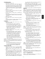
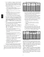
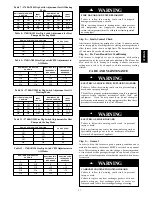
when primary heating source is used. (See Fig. 15--18.)
5. Dehumidify
Capability
with
Standard
Humidistat
Connection
Latent capabilities for systems using the variable--speed
oil--fired furnaces are better than average systems. If
increased latent capacity is an application requirement, the
field wiring terminal block provides connection terminals
for use of a standard humidistat.
The variable--speed oil--fired unit will detect the humidistat
contacts opening on increasing humidity and reduce its
airflow to approximately 85% of nominal cooling mode
airflow. This reduction will increase the system latent
capacity until the humidity falls to a level which causes the
humidistat contacts to close. When the contacts close, the
airflow will return to 100% of the selected cooling airflow.
To activate this mode, remove the Jumper between DH and
R of the electronic board and wire in a standard humidistat.
Filters
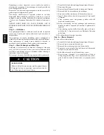
FIRE, CARBON MONOXIDE POISONING HAZARD
Failure to follow this warning could result in personal
injury, death and/or property damage.
Never operate unit without a filter or with filter access door
removed.
!
WARNING
An internal filter rack is provided as standard equipment with
furnace and is located in blower compartment. A sufficient
clearance should be provided for air filter access. Refer to Table 4
for filter rack flange dimensions for return air duct.
Table 4 – Filter Size and Quantity
UNIT
SIZE
AIR FILTER SIZE
IN (mm)
FLANGE OPENING SIZE
IN (mm)
036105
16 x 24 x 1
(406 x 609 x 25)
or
16 x 25 x 1
(406 x 635 x 25)
15 x 23
(381 x 584)
060120
20 x 30 x 1
(508 x 762 x 25)
19 x 29
(483 x 737)
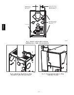
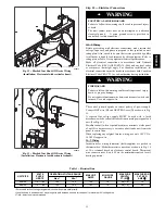
Step 11 — Horizontal or Downflow Installation
For horizontal installation, determine which “side” will become the
“top” when the unit is laid down. Remove the flue pipe clearance
knock--out from the top of that side panel. Install the flue elbow so
that it exits the cabinet of the furnace through that opening.
For counterflow installation, the flue pipe must exit the cabinet
through 1 of the side panel openings (as above), then extended up
the side of the furnace. Insure that adequate clearances to
combustibles are observed. Downflow Conversion/Vent Guard Kit
MUST be used.
Remove burner by loosening mounting nuts and turn oil burner
slightly counter--clockwise to unlock the keyhole burner flange.
Prevent putting undue strain on burner wiring. (It may be
necessary to disconnect burner wiring in some cases.)
To reinstall burner, insert on the four burner studs on keyhole
burner flange and turn it clockwise to lock it and tighten nuts.
IMPORTANT
: Burner must always be installed in the upright
position with ignition control on top.
START--UP, ADJUSTMENT, AND SAFETY
CHECKOUT
Step 1 — Operational Checkout
Installation of furnace is now complete. Perform the following
checkout procedures.
1. Correct nozzle size has been selected for desired input rate.
2. Electrical wiring is completed according to Fig. 14.
3. Blower wheel support is removed.
4. Blower access door is secured in place.
5. Valve on oil supply line is open.
6. RESET BUTTON on primary control is pushed down.
7. Flame observation door is closed.
8. Thermostat is set for heating mode and set above room
temperature.
If all of the above items have been performed, set main electrical
switch to ON position and burner should start. When burner starts,
proceed to Combustion Check section.
Step 2 — Sequence of Operation
Using schematic diagram in Fig. 14 follow the sequence of
operation through the different modes. Read and follow diagram
very carefully.
NOTE
: The GE ICM2+ blower motor speeds are infinitely--
variable control--airflow rate (CFM). The ICM2+ motor ramps to
speed at a controlled rate to reduce start--up noise perception. The
ICM2+ motor ramps down slowly to a stop in the same time as
ramp--up time. ICM2+ ramp--up and ramp--down times are additive
to blower--on and --off delays, respectively. The ICM2+ is 115--v
energized whenever power is available at furnace control, but
operates only when 24--v motor control input(s) are on.
374RAN


