CHAPTER 7 SERVICE SUPPORT SOFTWARE
7-24
How to rewrite
1.
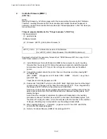
Controller firmware (ROM 1)
(BLF file)
(1)
Connect the USB cable to the printer. Turn on the printer while pressing Go and Job
Cancel keys. (The USB serial number is fixed to “987654321”.)
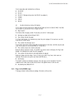
The LCD shows [SELF TEST] -> [RAM SIZE = 32MB] -> [Now Initializing] ->
[LINETEST MODE] in this order. Keep pressing Go and Job Cancel keys until
[LINETEST MODE] appears and release the keys after confirming it.
The LCD shows [WARMING UP] -> [READY] in this order. Wait until [READY] is
displayed.
(2) During the step (1), Plug and Play will run to install the USB driver of relevant model.
(3)
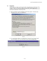
Double click “FILEDG32”, which is in the “AML” folder. Then, drug and drop the
firmware, LZ0173-$.BLF, to the printer icon in FILEDG32.
Data is sent to the printer via the USB cable and firmware rewriting starts. While the
data is sent to the printer, DATA LED blinks and when firmware rewriting starts, LED
display changes.
Even if transfer command is completed, the data is still transmitted or the rewriting
procedure continues. Therefore, be sure NOT to shut down the Windows system, turn
the printer off, unplug the cable, or turn the computer off until it reaches to the
condition of step (4). Rewriting may be impossible once the writing procedure fails.
(4)
After the rewriting finishes, the printer will be rebooted. Wait until Status LED of the
printer turns on in green. After rebooting, the copy 2 icon of the printer is created in
the printer folder. To avoid unnecessary mistake, delete the icon.
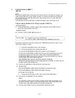
(PIT3)
(5)
Connect the USB cable to the printer. Turn on the printer while pressing Go and Job
Cancel keys. (The USB serial number is fixed to “987654321”.)
The LCD shows [SELF TEST] -> [RAM SIZE = 32MB] -> [Now Initializing] ->
[LINETEST MODE] in this order. Keep pressing Go and Job Cancel keys until
[LINETEST MODE] appears and release the keys after confirming it.
The LCD shows [WARMING UP] -> [READY] in this order. Wait until [READY] is
displayed.
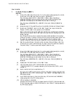
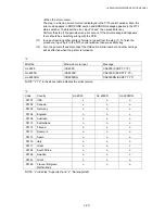
(6) Double-click “PIT3.EXE” which is in the “AML” folder.
(7) Input the model name in PIT3 control window, then press Enter key.
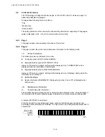
“CSXXXX”(SCRPTY.YY)” message appears in the model section of PIT3 control
window. *2
(8) Input a country code, then press Enter key. *3
EX: If you input “.00101” (USA version), “00101 (USA/USA)” message appears in the
specification section of PIT3 control window. Then, “READY” message appears in the
PIT3 status window.
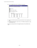
(9) Input 9 digits serial number, then press Enter key. PIT3 will start and “RUNNING”
message appears in the PIT3 status window.
(10) <When rewriting is completed>
“SER:VVVVVVVVVVVVVVVVVV” message appears in the PIT3 control window and
“PASS” message appears in ERR CODE section. Also, “READY” message appears in
the PIT3 status window.
Содержание HL-6050DN
Страница 188: ...HL 6050 6050D 6050DN SERVICE MANUAL 5 15 5 Put the paper tray into the printer Fig 5 29 Paper tray ...
Страница 190: ...HL 6050 6050D 6050DN SERVICE MANUAL 5 17 5 Remove the separation plate ASSY Fig 5 32 Separation plate ASSY ...
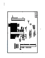
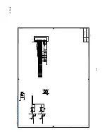
Страница 303: ...APPENDIX A 7 A 7 APPENDIX 7 BLOCK DIAGRAM HL 6050 CODE NAME LJ9586001 BLOCK DIAGRAM ...
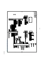
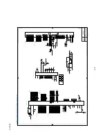
Страница 304: ...APPENDIX A 8 A 8 APPENDIX 8 LOW VOLTAGE POWER SUPPLY CIRCUIT DIAGRAM 100V HL 6050 NAME Low voltage PS Circuit 100V ...
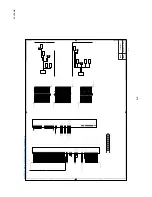
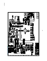
Страница 305: ...APPENDIX A 9 A 9 APPENDIX 9 LOW VOLTAGE POWER SUPPLY CIRCUIT DIAGRAM 200V HL 6050 NAME Low voltage PS Circuit 200V ...
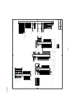
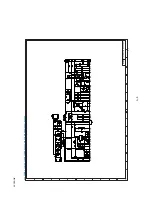
Страница 306: ...APPENDIX A 10 A 10 APPENDIX 10 HIGH VOLTAGE POWER SUPPLY CIRCUIT DIAGRAM HL 6050 NAME High voltage PS Circuit ...


