HL-6050/6050D/6050DN SERVICE MANUAL
5-9
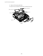
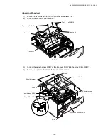
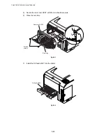
3) Open the rear tray.
4) Remove the two shoulder screws, and remove the rear cover ASSY.
Fig.5-18
5) Disconnect the two connectors.
6) Remove the two cup S M3x6 Taptite screws, and remove the fixing unit.
Fig.5-19
Fixing unit
Taptite, cup S M3x6
Rear cover ASSY
Shoulder
screws
Rear tray
1
2
3
Содержание HL-6050DN
Страница 188: ...HL 6050 6050D 6050DN SERVICE MANUAL 5 15 5 Put the paper tray into the printer Fig 5 29 Paper tray ...
Страница 190: ...HL 6050 6050D 6050DN SERVICE MANUAL 5 17 5 Remove the separation plate ASSY Fig 5 32 Separation plate ASSY ...
Страница 303: ...APPENDIX A 7 A 7 APPENDIX 7 BLOCK DIAGRAM HL 6050 CODE NAME LJ9586001 BLOCK DIAGRAM ...
Страница 304: ...APPENDIX A 8 A 8 APPENDIX 8 LOW VOLTAGE POWER SUPPLY CIRCUIT DIAGRAM 100V HL 6050 NAME Low voltage PS Circuit 100V ...
Страница 305: ...APPENDIX A 9 A 9 APPENDIX 9 LOW VOLTAGE POWER SUPPLY CIRCUIT DIAGRAM 200V HL 6050 NAME Low voltage PS Circuit 200V ...
Страница 306: ...APPENDIX A 10 A 10 APPENDIX 10 HIGH VOLTAGE POWER SUPPLY CIRCUIT DIAGRAM HL 6050 NAME High voltage PS Circuit ...


