


IV-5
3.2
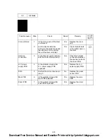
Troubleshooting Image Defects
The following procedures should be followed in the event of specific image defects.
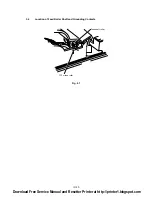
See subsection 3.3 for information about the location of the high-voltage contacts and
grounding contacts.
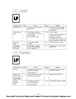
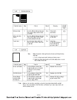
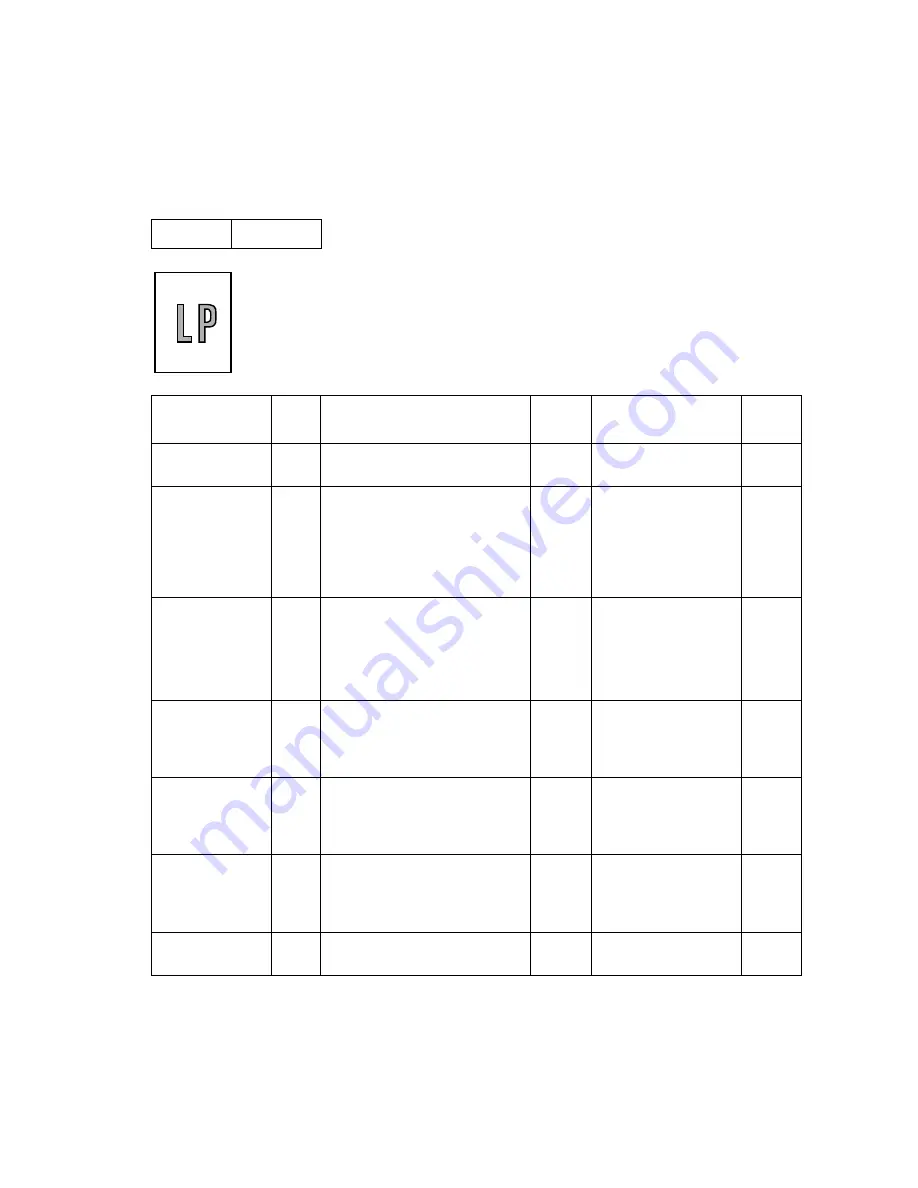
I-1
Light
Possible cause
Step
Check
Result
Remedy
HV.GND
contacts
(Fig.4-5)
Density dial
1
Is the density dial in the center
of the click position?
No
Set it to the center
detect position.
Toner sensing
failure
(printer side)
2
Can printing be started with the
drum unit removed?
Yes
Toner sensor failure.
Check if the toner
sensor needs
cleaning and check
the toner sensor
connection.
Toner sensing
failure
(toner cartridge
side)
3
Is the problem solved when 4
or 5 pages are printed after the
toner cartridge is replaced with
a full one?
Yes
The wiper of the
toner cartridge is
defective.
Replace the toner
cartridge.
Drum
connection
failure
4
Is all the contacts (HV, GND)
connected with electrode when
the drum unit is installed?
No
Clean contact
electrodes both in the
printer body and on
the drum unit.
➀
High-voltage
power supply
PCB failure
5
Check the harness connection
between the high-voltage
power supply PCB and the
driver PCB.
No
If the connection is
normal, replace the
high-voltage power
supply PCB.
Driver PCB or
main PCB
failure
6
Perform the same check as
step 5 above and also between
the driver PCB and the main
PCB.
No
Replace the driver
PCB or the main
PCB.
Scanner unit
failure
7
Is the problem solved by
repealing the scanner unit?
Yes
Replace the scanner
unit.
Download Free Service Manual and Resetter Printer at http://printer1.blogspot.com
Содержание HL-1070
Страница 1: ...Download Free Service Manual and Resetter Printer at http printer1 blogspot com ...
Страница 20: ...II 4 Fig 2 4 Download Free Service Manual and Resetter Printer at http printer1 blogspot com ...
Страница 29: ...II 13 Fig 2 14 Download Free Service Manual and Resetter Printer at http printer1 blogspot com ...
Страница 96: ...CODE UK3958 000 B48K302 1CIR NAME A 3 Appendix 3 Main PCB Circuit Diagram 1 5 ...
Страница 97: ...CODE UK3958 000 B48K302 1CIR NAME A 4 Appendix 4 Main PCB Circuit Diagram 2 5 ...
Страница 98: ...CODE UK3958 000 B48K302 1CIR NAME A 5 Appendix 5 Main PCB Circuit Diagram 3 5 ...
Страница 99: ...CODE UK3958 000 B48K302 1CIR NAME A 6 Appendix 6 Main PCB Circuit Diagram 4 5 ...
Страница 100: ...Appendix 7 Main PCB Circuit Diagram 5 5 CODE UK3958 000 B48K302 1CIR NAME A 7 ...
Страница 101: ...Appendix 8 Driver PCB Circuit Diagram CODE UK3634000 B48K280CIR NAME A 8 ...
Страница 102: ...Appendix 9 Switch Panel Solenoid Bin Relay PCB Circuit Diagram CODE UK3635000 281 282 283 CIR NAME A 9 ...
Страница 106: ...Appendix 13 SR PCB Circuit Diagram CODE UK3653000 B48K284CIR NAME A 13 ...
Страница 107: ...Apr 98 54U011BE0 PARTS REFERENCE LIST MODEL HL 1070 R LASER PRINTER ...
Страница 120: ...1 3 2 1 MODEL HL 1070 54U S03 151 8 DRIVER PCB MODEL HL 1070 54U S03 200 201 9 POWER SUPPLY PCB 11 ...
Страница 241: ...APPENDIX A 11 HP LaserJet 6P EPSON FX 850 IBM Proprinter XL EPSON FX 850 PC 850 ...


