


III-3
3. DISASSEMBLY
PROCEDURE
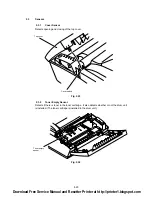
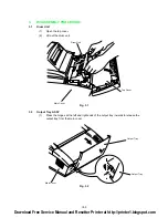
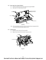
3.1
Drum Unit
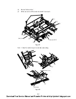
(1)
Open the top cover.
(2)
Lift out the drum unit.
Fig. 3.1
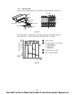
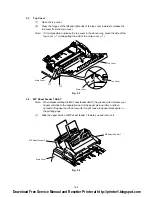
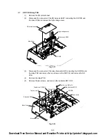
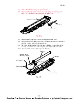
3.2
Output Tray ASSY
(1)
Press the hinges at the left and right ends of the output tray inwards to release the
output tray from the main cover.
Fig. 3.2
Drum Unit
Top Cover
Main Cover
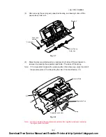
Main Cover
Output Tray
Output Tray
Download Free Service Manual and Resetter Printer at http://printer1.blogspot.com
Содержание HL-1070
Страница 1: ...Download Free Service Manual and Resetter Printer at http printer1 blogspot com ...
Страница 20: ...II 4 Fig 2 4 Download Free Service Manual and Resetter Printer at http printer1 blogspot com ...
Страница 29: ...II 13 Fig 2 14 Download Free Service Manual and Resetter Printer at http printer1 blogspot com ...
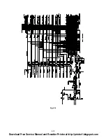
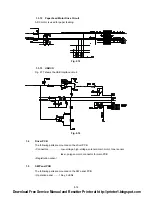
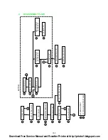
Страница 96: ...CODE UK3958 000 B48K302 1CIR NAME A 3 Appendix 3 Main PCB Circuit Diagram 1 5 ...
Страница 97: ...CODE UK3958 000 B48K302 1CIR NAME A 4 Appendix 4 Main PCB Circuit Diagram 2 5 ...
Страница 98: ...CODE UK3958 000 B48K302 1CIR NAME A 5 Appendix 5 Main PCB Circuit Diagram 3 5 ...
Страница 99: ...CODE UK3958 000 B48K302 1CIR NAME A 6 Appendix 6 Main PCB Circuit Diagram 4 5 ...
Страница 100: ...Appendix 7 Main PCB Circuit Diagram 5 5 CODE UK3958 000 B48K302 1CIR NAME A 7 ...
Страница 101: ...Appendix 8 Driver PCB Circuit Diagram CODE UK3634000 B48K280CIR NAME A 8 ...
Страница 102: ...Appendix 9 Switch Panel Solenoid Bin Relay PCB Circuit Diagram CODE UK3635000 281 282 283 CIR NAME A 9 ...
Страница 106: ...Appendix 13 SR PCB Circuit Diagram CODE UK3653000 B48K284CIR NAME A 13 ...
Страница 107: ...Apr 98 54U011BE0 PARTS REFERENCE LIST MODEL HL 1070 R LASER PRINTER ...
Страница 120: ...1 3 2 1 MODEL HL 1070 54U S03 151 8 DRIVER PCB MODEL HL 1070 54U S03 200 201 9 POWER SUPPLY PCB 11 ...
Страница 241: ...APPENDIX A 11 HP LaserJet 6P EPSON FX 850 IBM Proprinter XL EPSON FX 850 PC 850 ...


