


CHAPTER 4 OPTIONS
4–7
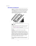
The following type of SIMMs can be installed:
• 1 MByte HITACHI HB56D25632B-6A, -7A
• 2 MByte HITACHI HB56D51232B-6A, -7A
• 4 MByte HITACHI HB56A132BV-7A, 7AL, -7B, -7BL
• 8 MByte HITACHI HB56A232BT-7A, -7AL, -7B, -7BL
• 16 MByte TOSHIBA THM324000BSG-70
• 32 MByte TOSHIBA THM328020BSG-70
This printer can accept the following types of SIMMs;
Speed
60 nsec - 80 nsec
Pin Type
72 pin
Height
25.4 mm (1") or less
Output
32 bit or 36 bit
✒
Note
The printer has only one slot for a SIMM upgrade.If you want to increase
your printer memory again after you have installed a SIMM module into
the slot, you will need to remove the previously installed SIMM first. For
example if you have previously increased your memory from the standard
4 MB to 8 MB by adding a 4 MB SIMM and you wish to increase your
total memory to 12 MB, you need to remove the installed 4 MB SIMM
and install the new 8 MB SIMM into the printer.
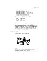
Installing the SIMM
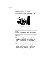
When you install the SIMM, follow these steps:
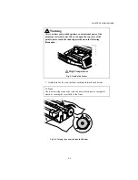
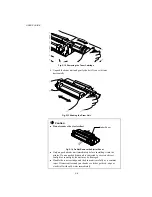
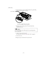
1. Turn off the power switch and unplug the power cord from the AC
outlet. Then, disconnect the interface cable from the printer.
Fig. 4-3 Unplug the power cord and
disconnect the interface cable
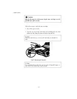
✒
Note
Be sure to unplug the power cord to the printer before installing or
removing the SIMM and the main controller board.
Содержание HL-1070
Страница 1: ...Download Free Service Manual and Resetter Printer at http printer1 blogspot com ...
Страница 20: ...II 4 Fig 2 4 Download Free Service Manual and Resetter Printer at http printer1 blogspot com ...
Страница 29: ...II 13 Fig 2 14 Download Free Service Manual and Resetter Printer at http printer1 blogspot com ...
Страница 96: ...CODE UK3958 000 B48K302 1CIR NAME A 3 Appendix 3 Main PCB Circuit Diagram 1 5 ...
Страница 97: ...CODE UK3958 000 B48K302 1CIR NAME A 4 Appendix 4 Main PCB Circuit Diagram 2 5 ...
Страница 98: ...CODE UK3958 000 B48K302 1CIR NAME A 5 Appendix 5 Main PCB Circuit Diagram 3 5 ...
Страница 99: ...CODE UK3958 000 B48K302 1CIR NAME A 6 Appendix 6 Main PCB Circuit Diagram 4 5 ...
Страница 100: ...Appendix 7 Main PCB Circuit Diagram 5 5 CODE UK3958 000 B48K302 1CIR NAME A 7 ...
Страница 101: ...Appendix 8 Driver PCB Circuit Diagram CODE UK3634000 B48K280CIR NAME A 8 ...
Страница 102: ...Appendix 9 Switch Panel Solenoid Bin Relay PCB Circuit Diagram CODE UK3635000 281 282 283 CIR NAME A 9 ...
Страница 106: ...Appendix 13 SR PCB Circuit Diagram CODE UK3653000 B48K284CIR NAME A 13 ...
Страница 107: ...Apr 98 54U011BE0 PARTS REFERENCE LIST MODEL HL 1070 R LASER PRINTER ...
Страница 120: ...1 3 2 1 MODEL HL 1070 54U S03 151 8 DRIVER PCB MODEL HL 1070 54U S03 200 201 9 POWER SUPPLY PCB 11 ...
Страница 241: ...APPENDIX A 11 HP LaserJet 6P EPSON FX 850 IBM Proprinter XL EPSON FX 850 PC 850 ...


