


USER’S GUIDE
5–6
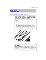
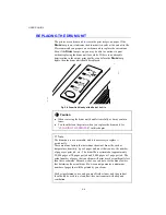
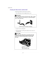
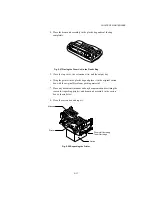
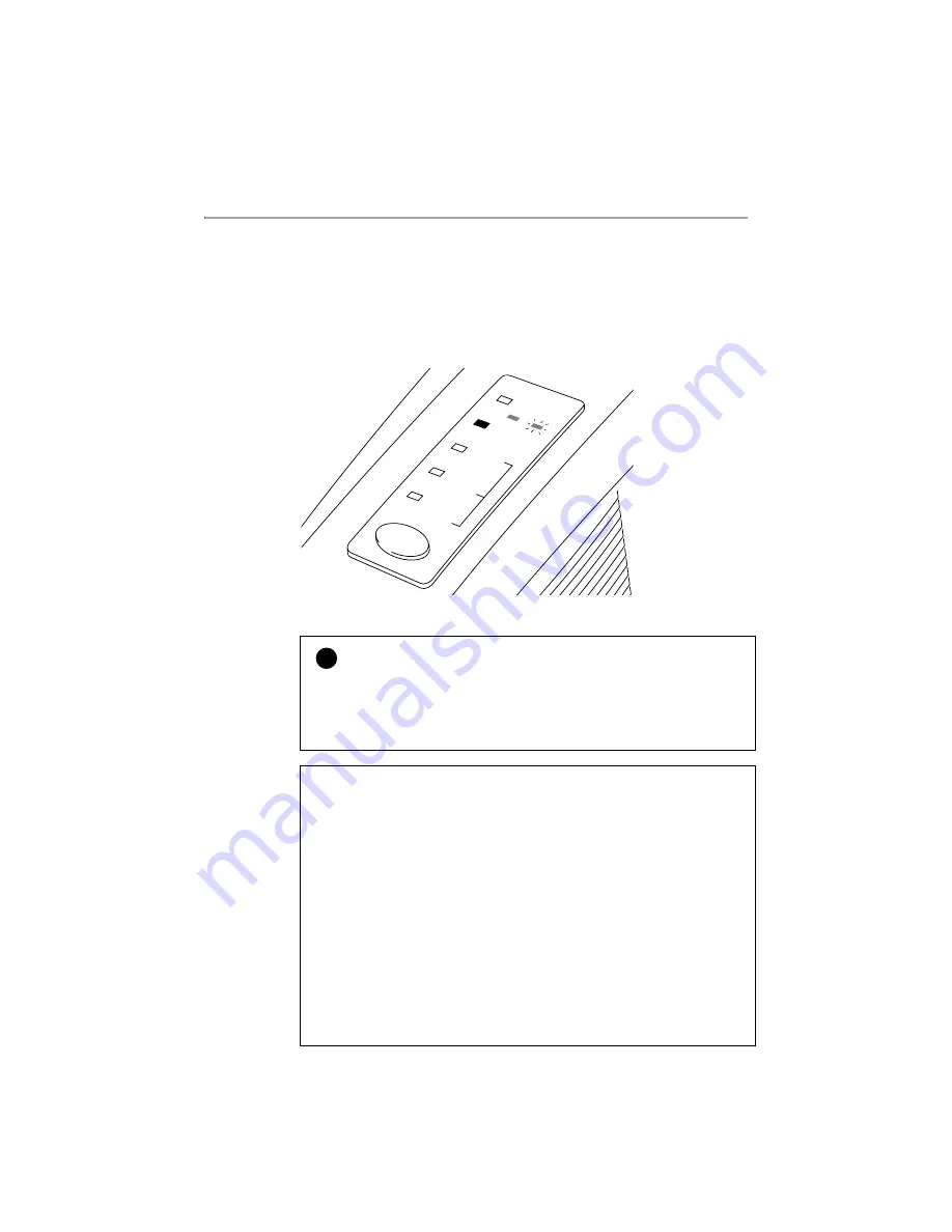
REPLACING THE DRUM UNIT
The printer uses a drum unit to create the print images on paper. If the
Drum
lamp is on, it indicates the drum unit is nearly at the end of its life.
We recommend you prepare a new drum unit to replace the current one.
Even if the
Drum
lamp is on, you may be able to continue to print
without replacing the drum unit for a while. If there is a noticeable
deterioration in the output print quality even before the
Drum
lamp
lights, then the drum unit should be replaced.
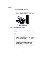
Feeder
Drum
Alarm
Ready
Paper
Data
Toner
1 2
Fig. 5-9 Drum Unit Nearly at the End of its Life
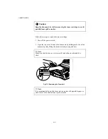
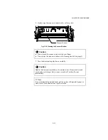
!
Caution
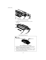
When removing the drum unit, handle it carefully as it may contain
toner.
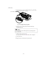
You should clean the printer when you replace the drum unit.
See
“CLEANING THE PRINTER”
in this chapter.
✒
Note
The drum unit is a consumable, and it is necessary to replace it
periodically.
There are many factors that determine the actual drum life, such as
temperature, humidity, type of paper and toner that you use, the number
of pages per print job, etc.. The drum life is estimated at approximately
20,000 pages at 20 pages per job and 8,000 pages at 1 page per job. The
actual number of pages that your drum will print may be significantly less
than these estimates. Because we have no control over the many factors
that determine the actual drum life, we cannot guarantee a minimum
number of pages that will be printed by your drum.
For best performance, use only genuine Brother toner, and the product
should only be used in a clean, dust-free environment with adequate
ventilation.
Содержание HL-1070
Страница 1: ...Download Free Service Manual and Resetter Printer at http printer1 blogspot com ...
Страница 20: ...II 4 Fig 2 4 Download Free Service Manual and Resetter Printer at http printer1 blogspot com ...
Страница 29: ...II 13 Fig 2 14 Download Free Service Manual and Resetter Printer at http printer1 blogspot com ...
Страница 96: ...CODE UK3958 000 B48K302 1CIR NAME A 3 Appendix 3 Main PCB Circuit Diagram 1 5 ...
Страница 97: ...CODE UK3958 000 B48K302 1CIR NAME A 4 Appendix 4 Main PCB Circuit Diagram 2 5 ...
Страница 98: ...CODE UK3958 000 B48K302 1CIR NAME A 5 Appendix 5 Main PCB Circuit Diagram 3 5 ...
Страница 99: ...CODE UK3958 000 B48K302 1CIR NAME A 6 Appendix 6 Main PCB Circuit Diagram 4 5 ...
Страница 100: ...Appendix 7 Main PCB Circuit Diagram 5 5 CODE UK3958 000 B48K302 1CIR NAME A 7 ...
Страница 101: ...Appendix 8 Driver PCB Circuit Diagram CODE UK3634000 B48K280CIR NAME A 8 ...
Страница 102: ...Appendix 9 Switch Panel Solenoid Bin Relay PCB Circuit Diagram CODE UK3635000 281 282 283 CIR NAME A 9 ...
Страница 106: ...Appendix 13 SR PCB Circuit Diagram CODE UK3653000 B48K284CIR NAME A 13 ...
Страница 107: ...Apr 98 54U011BE0 PARTS REFERENCE LIST MODEL HL 1070 R LASER PRINTER ...
Страница 120: ...1 3 2 1 MODEL HL 1070 54U S03 151 8 DRIVER PCB MODEL HL 1070 54U S03 200 201 9 POWER SUPPLY PCB 11 ...
Страница 241: ...APPENDIX A 11 HP LaserJet 6P EPSON FX 850 IBM Proprinter XL EPSON FX 850 PC 850 ...


