G730-Install-IG100 Installation Guide
Brocade
®
G730 Switch Hardware Installation Guide
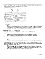
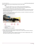
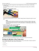
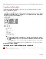
2. Position a cable so that the key (the ridge on one side of the cable connector) is aligned with the slot in the transceiver.
Insert the cable into the transceiver until the latching mechanism clicks.
Figure 27: Installing SFP+ Cables
1. Cable and Connector
2. Transceiver
NOTE
Cables are keyed so that they can be inserted in only one way. If a cable does not slide in easily, ensure that
it is correctly oriented. Do not insert any unsupported cable that is intended for another type of transceiver
into a regular SFP+ transceiver. You may damage the cable as well as the transceiver.
Replacing an SFP+ Transceiver
Perform the following steps to remove an SFP+ transceiver and then install a new SFP+ transceiver:
NOTE
•
Replacing an SFP+ transceiver may cause disruption in the fabric or to the attached device.
•
Always use the pull tab to insert or remove an SFP+ transceiver, since the SFP might be hot.
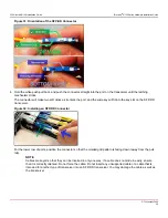
1. Remove any cables that are inserted into the transceiver.
2. Grasp the SFP+ transceiver pull tab, and pull the tab straight out.
NOTE
Grasp the tab near the body of the transceiver to reduce the chances of bending the pull tab. Avoid touching
the transceiver because it may be hot.
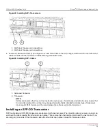
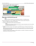
3. To insert the replacement transceiver, use the pull tab on the SFP+ transceiver to carefully push the transceiver into
the port. Transceivers are keyed so that they can be inserted only with the correct orientation. If a transceiver does not
slide in easily, ensure that it is correctly oriented.
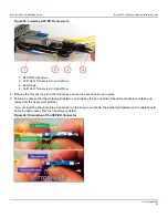
NOTE
Each SFP+ transceiver has a 10-pad gold-plated PCB-edge connector on the bottom. The correct position
to insert an SFP+ transceiver into the upper row of ports is with the gold edge down. The correct position to
insert an SFP+ transceiver into the lower row of ports is with the gold edge up.
G730-Install-IG100
53
Содержание Brocade G730
Страница 94: ......

