background image

G730-Install-IG100 Installation Guide


Brocade

®

 G730 Switch Hardware Installation Guide

2.

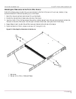
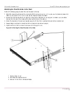
Attaching the Front Brackets to the Rack

3.

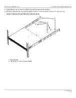
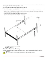
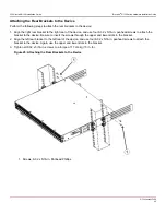
Attaching the Rear Brackets to the Rack

4.

Attaching the Rear Brackets to the Device

Attaching the Front Brackets to the Device

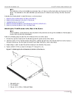
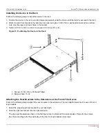
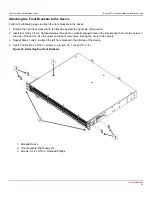
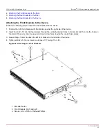
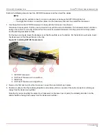
Perform the following steps to attach the front brackets to the device:
1. Position the right front bracket with the flat side against the right side of the device.
2. Insert four 8-32 x 5/16-in. flathead screws through the vertically aligned holes in the bracket and then into the holes on

the side of the device. Use the upper and lower screw holes, leaving the center holes empty.

3. Repeat Steps 1 and 2 to attach the left front bracket to the left side of the device.
4. Tighten all 8-32 x 5/16-in. screws to a torque of 17 cm-kg (15 in.-lb).

Figure 22: Attaching the Front Brackets

1. Brocade Device

2. Front Brackets, Right and Left

3. Screws, 8-32 x 5/16-in. Flathead Phillips


G730-Install-IG100

40

Содержание Brocade G730

Страница 1: ...Brocade G730 Switch Hardware Installation Guide Installation Guide 15 December 2021 G730 Install IG100 15 December 2021 ...

Страница 2: ...Laser Precautions 14 Facility Requirements 14 Quick Installation Checklist 15 Shipping Carton Contents 18 Mounting the Device 19 Precautions Specific to Mounting 19 Installing the Device as a Stand alone Unit 20 Installing the Universal Four Post Rack Kit XBR R000296 20 Time and Items Required 20 Parts List 21 Flush Front Mounting 22 Attaching the Front Brackets 23 Attaching the Extension Brackets...

Страница 3: ...he Rear Brackets to the Device 43 Initial Setup and Verification 44 Items Required 44 Providing Power to the Device 44 Establishing a First Time Serial Connection 44 Configuring the IP Address 45 Using DHCP to Set the IP Address 46 Setting a Static IP Address 46 Setting the Date and Time 46 Setting the Time Zone 47 Synchronizing the Local Time with an External Source 47 Customizing the Chassis Nam...

Страница 4: ...ly Airflow 67 Power Supply Assembly Fault Indicators 67 Power Supply Assembly Task Guide 68 Time and Items Required 68 Recording Critical Information about the Power Supply Assembly 69 Removing a Power Supply Assembly 69 Inserting a New Power Supply Assembly 69 Fan Assemblies 71 Precautions Specific to the Fan Assemblies 72 Identifying the Direction of the Fan Assembly Airflow 72 Fan Assembly Faul...

Страница 5: ...hina ROHS 82 FCC Warning U S Only 82 Germany Statement 82 KCC Statement Republic of Korea 82 Taiwan ROHS Certification 83 VCCI Statement 83 Regulatory Compliance 84 Cautions and Danger Notices 85 Cautions 85 Danger Notices 88 Revision History 92 Copyright Statement 93 G730 Install IG100 5 ...

Страница 6: ...nport side intake airflow XBR ENT FAN 80 F 2 Fan assembly FRU with nonport side exhaust airflow XBR ENT FAN 80 R 2 Fan assembly FRU with nonport side intake airflow Table 2 Rack Mount Kits Part Number Description XBR R000294 Universal two post mid mount or flush mount rack kit XBR R000296 Universal four post fixed flush mount rack kit Notes Cautions and Danger Notices Notes cautions and danger sta...

Страница 7: ...ct brocade support Online Telephone For nonurgent issues the preferred method is to log on to the Support portal at support broadcom com You must initially register to gain access to the Support portal Once registered log on and then select Brocade Products You can now navigate to the following sites Case Management Software Downloads Licensing SAN Reports Brocade Support Link Training Education F...

Страница 8: ... and verification services for the physical media Brocade small form factor pluggable plus SFP optical transceivers that support any combination of short wavelength SWL long wavelength LWL or extended long wavelength ELWL optical media among the switch ports LEDs 96 bicolor green amber LEDs to indicate the status for each SFP port and 16 tricolor green amber white LEDs to indicate the status for e...

Страница 9: ...ion Integral LEDs remain unlit always One external USB Type A connector License Options The Brocade G730 Switch uses a capacity based Ports on Demand POD license method Refer to the Brocade Fabric OS Software Licensing Guide for more details Port Side View of the Device The following figure shows the port side view of the Brocade G730 Fibre Channel Switch Figure 1 Port Side View 1 System Power LED...

Страница 10: ...lies Fan 1 2 and 3 from right to left 3 Ground Cable Connector Device Management Options You can use the management functions built into the device to monitor the fabric topology port status physical status and other information This functionality helps you analyze switch performance and accelerate system debugging The device automatically performs a power on self test POST each time it is turned ...

Страница 11: ...tup EZSwitchSetup helps to complete the basic configuration for a single switch setup Ethernet or serial connection Brocade EZSwitchSetup User Guide Brocade Web Tools Ethernet or serial connection Brocade Fabric OS Web Tools User Guide Standard SNMP applications Ethernet or serial connection Brocade Fabric OS MIB Reference Manual Management Server Ethernet or serial connection Brocade Fabric OS Ad...

Страница 12: ...nsert your fingers into the fan tray while removing it from the chassis The fan may still be spinning at a high speed CAUTION Changes or modifications made to this device that are not expressly approved by the party responsible for compliance could void the user s authority to operate the equipment CAUTION Disassembling any part of the power supply and fan assembly voids the warranty and regulator...

Страница 13: ...th the device to connect it to the power source DANGER If the installation requires a different power cord than the one supplied with the device make sure you use a power cord displaying the mark of the safety agency that defines the regulations for power cords in your country The mark is your assurance that the power cord can be used safely with the device DANGER This device might have more than ...

Страница 14: ...d Weight Related Precautions DANGER Use safe lifting practices when moving the product DANGER Mount the devices you install in a rack as low as possible Place the heaviest device at the bottom and progressively place lighter devices above DANGER Make sure the rack housing the device is adequately secured to prevent it from becoming unstable or falling over CAUTION Do not use the port cover tabs to...

Страница 15: ...as specified by the electrical rating on the switch nameplate A circuit that is protected by a circuit breaker and grounded in accordance with local electrical codes See the Technical Specifications section for power supply specifications Thermal Ambient air temperature not exceeding 40 C 104 F while the switch is operating Rack when rack mounted All equipment in the rack grounded through a reliab...

Страница 16: ...ing the Device Installing Transceivers and Cables Power Supply Assemblies Fan Assemblies Review the safety precautions See Safety Precautions For the translation of these messages see Cautions and Danger Notices Plan the installation Decide whether you want to install the unit on a flat surface or in a rack For rack installation obtain the appropriate rack mount kit See Mounting the Device Review ...

Страница 17: ...serial port to configure the device Set the IP address the subnet mask and the default gateway IP address Use the ipaddrset command to configure a static device IP address subnet mask and gateway IP address or you can use a Dynamic Host Configuration Protocol DHCP server to obtain the information dynamically See Configuring the IP Address Set the date and time Use the date command to display and s...

Страница 18: ... up the configuration See Backing Up the Configuration for more information Optional Power off the device Enter the sysshutdown command and wait for the device to power down and then unplug the power cord See Powering Down the Device for more information Shipping Carton Contents When unpacking the device verify that the contents of the shipping carton are complete The shipping carton should contai...

Страница 19: ...unications Telco rack NOTE Review the following precautions before mounting the device Precautions Specific to Mounting The following precautions apply to mounting the device DANGER Use safe lifting practices when moving the product DANGER Mount the devices you install in a rack as low as possible Place the heaviest device at the bottom and progressively place lighter devices above CAUTION Make su...

Страница 20: ...de flush with the front posts With the nonport side flush with the rear posts in a recessed position A recessed position allows a more gradual bend in the fiber optic cables that are connected to the switch and less interference in the aisle at the front of the rack Table 7 Space Requirements Chassis with Port Side Vents Notes Chassis Depth Minimum Rack Depth Maximum Rack Depth No Applicable to po...

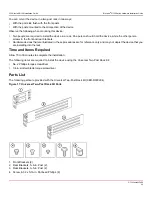
Страница 21: ...al Four Post Rack Kit No 2 Phillips torque screwdriver 1 4 in slotted blade torque screwdriver Parts List The following parts are provided with the 1U and 2U Universal Four Post Rack Kit XBR R000296 Figure 5 Universal Four Post Rack Kit Parts 1 Front Brackets 2 2 Extension Brackets Medium 2 3 Rear Brackets Short 2 4 Rear Brackets Long 2 G730 Install IG100 21 ...

Страница 22: ... device type CAUTION Use the screws specified in the procedure Using longer screws can damage the device Flush Front Mounting CAUTION The device must be turned off and disconnected from the fabric during this procedure NOTE The illustrations in the rack installation procedures are for reference only and may not show the device that you are installing Perform the following tasks to install the devi...

Страница 23: ...Insert four 8 32 x 5 16 in flathead screws through the vertically aligned holes in the bracket and then into the holes on the side of the device Use the upper and lower screw holes leaving the center holes empty 3 Repeat Step 1 and Step 2 to attach the left front bracket to the left side of the device 4 Tighten all 8 32 x 5 16 in screws to a torque of 17 cm kg 15 in lb Figure 6 Attaching the Front...

Страница 24: ...on bracket along the side of the device 3 Insert four 8 32 x 5 16 in flathead screws through the vertically aligned holes in the bracket extension and then into the holes on the side of the device Use the upper and lower screw holes leaving the center holes empty 4 Repeat Steps 2 and 3 to attach the left extension bracket to the left side of the device 5 Tighten all 8 32 x 5 16 in screws to a torq...

Страница 25: ...ll 10 32 x 5 8 in screws to a torque of 29 cm kg 25 in lb Figure 8 Positioning the Device in the Rack 1 Screws 10 32 x 5 8 in Panhead Phillips 2 Retainer Nuts 10 32 Attaching the Rear Brackets to the Extensions Perform the following steps to attach the rear brackets to the extensions You can use short or long rear brackets for this task depending on the depth of your rack 1 Select the proper lengt...

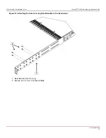
Страница 26: ... 3 to attach the left rear bracket to the left extension bracket 5 Adjust the brackets to the rack depth and tighten all 6 32 x 1 4 in screws to a torque of 10 cm kg 9 in lb Figure 9 Attaching the Rear Brackets to the Extensions 1 Rear Brackets 2 Screws 6 32 x 1 4 in Panhead Phillips G730 Install IG100 26 ...

Страница 27: ...ear bracket to the left rear rack post using two 10 32 x 5 8 in panhead screws and two retainer nuts Use the upper and lower holes in the bracket 3 Tighten all 10 32 x 5 8 in screws to a torque of 29 cm kg 25 in lb Figure 10 Attaching the Rear Brackets to the Rack Posts 1 Screws 10 32 x 5 8 in Panhead Phillips 2 Retainer Nuts 10 32 Flush Rear Recessed Mounting Flush rear recessed mounting is simil...

Страница 28: ... the Rear of the Device NOTE In this installation the brackets are named as listed in the parts list even though the installation of the brackets is reversed from the flush front installation Perform the following steps to attach the front brackets to the rear of the device 1 Position the right front bracket with the flat side against the right rear side of the device 2 Insert four 8 32 x 5 16 in ...

Страница 29: ...osition the right extension bracket along the side of the device 3 Insert four 8 32 x 5 16 in flathead screws through the vertically aligned holes in the extension brackets and then into the holes on the side of the device Use the upper and lower screw holes leaving the center holes empty 4 Repeat Steps 2 and 3 to attach the left front extension bracket to the left side of the device 5 Tighten all...

Страница 30: ...8 in screws to a torque of 29 cm kg 25 in lb Figure 13 Positioning the Device in the Rack 1 Screws 10 32 x 5 8 in Panhead Phillips 2 Retainer Nuts 10 32 Attaching the Rear Brackets to the Extensions at the Front of the Device Perform the following steps to attach the rear brackets to the extensions The rack depth determines the use of short or long brackets 1 Select the proper length rear bracket ...

Страница 31: ... Repeat Steps 2 and 3 to attach the left rear bracket to the left extension 5 Adjust the brackets to the rack depth and tighten all 6 32 x 1 4 in screws to a torque of 10 cm kg 9 in lb Figure 14 Attaching the Rear Brackets to the Extensions at the Front of the Device 1 Rear Brackets Short 2 Screws 6 32 x 1 4 in Panhead Phillips G730 Install IG100 31 ...

Страница 32: ...tallation Guide Brocade G730 Switch Hardware Installation Guide Figure 15 Attaching the Short or Long Rear Brackets to the Extensions 1 Rear Bracket Short or Long 2 Screws 6 32 x 1 4 in Panhead Phillips G730 Install IG100 32 ...

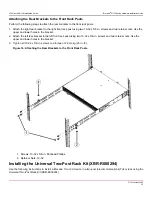
Страница 33: ...ach the left rear bracket to the left front rack post using two 10 32 x 5 8 in screws and two retainer nuts Use the upper and lower holes in the bracket 3 Tighten all 10 32 x 5 8 in screws to a torque of 29 cm kg 25 in lb Figure 16 Attaching the Rear Brackets to the Front Rack Posts 1 Screws 10 32 x 5 8 in Panhead Phillips 2 Retainer Nuts 10 32 Installing the Universal Two Post Rack Kit XBR R00029...

Страница 34: ...ces that are illustrated in these procedures are for reference only and may not depict the device that you are installing into the rack Time and Items Required Allow 15 to 30 minutes to complete the installation The following items are required to install the device using the Universal Two Post Rack Kit No 2 Phillips torque screwdriver 1 4 in slotted blade torque screwdriver Parts List The followi...

Страница 35: ... turned off and disconnected from the fabric during this procedure The figures in this document show a 1U device but the instructions are the same for a 2U device The figures for this procedure show a two post rack with narrow posts 3 in to 5 in as an example The figures in the rack installation procedures are for reference only and may not show the actual device CAUTION Use the screws specified i...

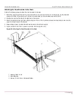
Страница 36: ...32 x 5 16 in flathead screws through the vertically aligned holes in the bracket and then into the holes on the side of the device Use the upper and lower screw holes leaving the center holes empty 3 Repeat Steps 1 and 2 to attach the left front bracket to the left side of the device 4 Tighten all the 8 32 x 5 16 in screws to a torque of 17 cm kg 15 in lb Figure 18 Attaching the Front Brackets 1 B...

Страница 37: ...he right front bracket to the right rack upright using two 10 32 x 5 8 in panhead screws and two retainer nuts Use the upper and lower holes in the bracket 3 Attach the left front bracket to the left rack upright using two 10 32 x 5 8 in panhead screws and two retainer nuts Use the upper and lower holes in the bracket 4 Tighten all the 10 32 x 5 8 in screws to a torque of 29 cm kg 25 in lb Figure ...

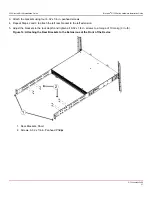
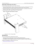
Страница 38: ...es wide use the brackets marked 5 6 INCH 2 Position the right rear bracket in the right rear of the device 3 Attach the bracket to the right rack upright using two 10 32 x 5 8 in panhead screws and two retainer nuts Use the upper and lower holes in the bracket 4 Repeat Steps 2 and 3 to attach the left rear bracket to the left rack upright 5 Tighten all the 10 32 x 5 8 in screws to a torque of 29 c...

Страница 39: ...racket to the device Again use the upper and lower slots in the bracket 3 Tighten all the 8 32 x 5 16 in screws to a torque of 17 cm kg 15 in lb Figure 21 Attaching the Rear Brackets to the Device 1 Screws 8 32 x 5 16 in Panhead Phillips Mid Mounting Observe the following notes when performing this procedure The device must be turned off and disconnected from the fabric during this procedure The i...

Страница 40: ...he flat side against the right side of the device 2 Insert four 8 32 x 5 16 in flathead screws through the vertically aligned holes in the bracket and then into the holes on the side of the device Use the upper and lower screw holes leaving the center holes empty 3 Repeat Steps 1 and 2 to attach the left front bracket to the left side of the device 4 Tighten all 8 32 x 5 16 in screws to a torque o...

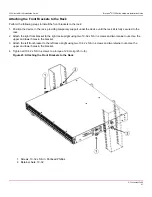
Страница 41: ...ack 2 Attach the right front bracket to the right rack upright using two 10 32 x 5 8 in screws and two retainer nuts Use the upper and lower holes in the bracket 3 Attach the left front bracket to the left rack upright using two 10 32 x 5 8 in screws and two retainer nuts Use the upper and lower holes in the bracket 4 Tighten all 10 32 x 5 8 in screws to a torque of 29 cm kg 25 in lb Figure 23 Att...

Страница 42: ...ght rear bracket in the right rear of the device Whether you are using the 3 5 INCH or the 5 6 INCH bracket the rear end of the bracket will be flush with the back of the device 3 Attach the brackets to the right rack upright using two 10 32 x 5 8 in panhead screws and two retainer nuts 4 Repeat Step 2 and Step 3 to attach the left rear bracket to the left rack upright 5 Tighten all 10 32 x 5 8 in...

Страница 43: ...d screws to attach the bracket to the device Be sure to insert the screws through the upper and lower slots in the bracket 2 Align the left rear bracket to the left rear of the device and use four 8 32 x 5 16 in panhead screws to attach the bracket to the device Again use the upper and lower slots in the bracket 3 Tighten all 8 32 x 5 16 in screws to a torque of 17 cm kg 15 in lb Figure 25 Attachi...

Страница 44: ...32GB DataTraveler 100 G3 USB 3 0 Flash Drive DT100G3 32GB Kingston 32GB DataTraveler G4 USB 3 0 Flash Drive DTIG4 32GB PNY Attache 3 0 4 USB 32GB Flash Drive PNY Attache 3 0 4 USB 16GB Flash Drive These drives are not orderable from Broadcom but are generically branded and can be purchased from other suppliers Providing Power to the Device Perform the following steps to provide power to the device...

Страница 45: ... ttyb 9600 If ttyb is already in use use ttya instead and enter the following string at the prompt tip dev ttya 9600 4 When the terminal emulator application stops reporting information press Enter to display the login prompt Switch Console Login 5 Log on to the device as admin using the default password password You are prompted to change the default user name and password at initial logon Make s...

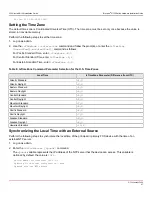
Страница 46: ...mpted DHCP OFF off Setting the Date and Time The date and time settings are used for event logging error detection and troubleshooting However device operation does not depend on the date and time a device with incorrect date or time values still functions properly You can synchronize the local time of the principal or primary fabric configuration server FCS device to that of an external Network T...

Страница 47: ...he U S Time Zones Local Time tsTimeZone Parameter Difference from UTC Atlantic Standard 4 0 Atlantic Daylight 3 0 Eastern Standard 5 0 Eastern Daylight 4 0 Central Standard 6 0 Central Daylight 5 0 Mountain Standard 7 0 Mountain Daylight 6 0 Pacific Standard 8 0 Pacific Daylight 7 0 Alaskan Standard 9 0 Alaskan Daylight 8 0 Hawaiian Standard 10 0 Synchronizing the Local Time with an External Sourc...

Страница 48: ...ation 3 Connect an Ethernet cable to the device Ethernet port and to the workstation or an Ethernet network that connects the workstation NOTE At this point the device can be accessed remotely using either the command line or Brocade Web Tools Ensure that the device is not being modified from any other connections during the remaining tasks in this chapter The Ethernet management port also support...

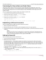
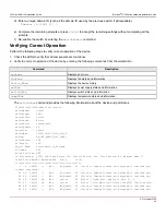
Страница 49: ...chShow command provides the following information about the device and port status G730switch FID128 admin switchshow switchName ras030 switchType 189 3 switchState Online switchMode Native switchRole Subordinate switchDomain 30 switchId fffc1e switchWwn 10 00 c4 f5 7c 02 31 98 zoning ON WB_RAS159_64G_LSAN switchBeacon OFF FC Router OFF Fabric Name Serviceability_Testbed HIF Mode OFF Allow XISL Us...

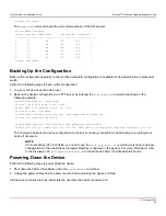
Страница 50: ...ser anonymous Path Filename home dir config txt home dumps config fid100 txt Section all chassis FID all configUpload complete All selected config parameters are uploaded 2020 03 05 23 57 59 CONF 1001 130 FID 128 INFO device configUpload completed successfully for all This command uploads the device configuration to the server making it available for downloading to a replacement device if necessar...

Страница 51: ...r optic reel type cleaner When not using a connector make sure to keep the protective covering in place Managing Cables The minimum bend radius for a 50 micron cable is 2 in under a full tensile load and 1 2 in with no tensile load Cables can be organized and managed in various ways for example using cable channels on the sides of the rack or patch panels to minimize cable management Follow these ...

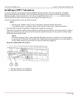
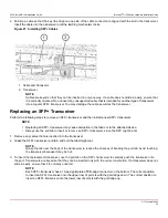
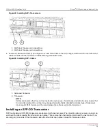
Страница 52: ...t find it easier to insert the cables into the transceiver first and then install the transceiver 1 Use the pull tab on the SFP transceiver to help push the transceiver into the port Transceivers are keyed so that they can be inserted only with the correct orientation If a transceiver does not slide in easily ensure that it is correctly oriented Push the correctly oriented transceiver into the por...

Страница 53: ...se disruption in the fabric or to the attached device Always use the pull tab to insert or remove an SFP transceiver since the SFP might be hot 1 Remove any cables that are inserted into the transceiver 2 Grasp the SFP transceiver pull tab and pull the tab straight out NOTE Grasp the tab near the body of the transceiver to reduce the chances of bending the pull tab Avoid touching the transceiver b...

Страница 54: ...eyed so that they can be inserted in only one way If a cable does not slide in easily ensure that it is correctly oriented Do not insert any unsupported cable that is intended for another type of transceiver into a regular SFP transceiver You may damage the cable as well as the transceiver Installing an SFP DD Transceiver SFP double density SFP DD transceivers are delivered with two dust caps When...

Страница 55: ...nted transceiver into the port until it is firmly seated and the latching mechanism clicks For the top row of ports insert the transceiver so that the pull tab is on the bottom For the bottom row of ports insert the transceiver so that the pull tab is on the top Figure 30 Installing SFP DD Transceivers 1 SFP DD Transceiver 2 Pull Tab of Transceiver in Lower Row 3 Dust Caps 4 Pull Tab of Transceive...

Страница 56: ...the key slot on the SFP DD transceiver Figure 32 Installing an SFP DD Connector For the lower row of ports position the connector so that the molded grid pattern is facing down away from the pull tab NOTE Cables are keyed so that they can be inserted in only one way If a cable does not slide in easily ensure that it is correctly oriented Do not force the cable Do not insert any unsupported cable o...

Страница 57: ...FP DD transceiver pull tab and pull the tab straight out NOTE Grasp the tab near the body of the transceiver to reduce the chances of bending the pull tab Avoid touching the transceiver because it may be hot 3 To insert the replacement transceiver use the pull tab on the SFP DD transceivers to help push the transceiver into the port Transceivers are keyed so that they can be inserted only with the...

Страница 58: ...t dust cap from the transceiver Leave the second dust cap in place 5 Position a cable so that the molded grid pattern and wide key tab on one side of the cable connector are facing up away from the transceiver pull tab If you are inserting the cable into a transceiver on the lower row of ports the molded grid pattern on the cable should be facing down away from the transceiver pull tab Figure 35 O...

Страница 59: ...y If a cable does not slide in easily ensure that it is correctly oriented Do not force the cable Do not insert any unsupported cable or a cable that is intended for another type of transceiver into an SFP DD transceiver You may damage the cable as well as the transceiver 7 Gently tug on the cable to make sure that it is seated firmly Figure 37 SFP DD Connectors Correctly Inserted Remove the secon...

Страница 60: ...tus in green or amber All functionality pertaining to the green amber colors for the last 16 LEDs remains the same as the first 96 LEDs The LEDs have three possible states no light a steady light and a flashing light Flashing lights may be slow fast or flickering The lights are green or amber Sometimes the LEDs may flash any of the colors during boot POST or other diagnostic tests This flashing is...

Страница 61: ... no power Verify that the system is on and has completed booting Steady green The POST and initialization have completed The system is on and functioning properly No action is required Steady amber for more than 5 seconds can take over a minute to complete the POST The system is going through the power up process No action is required Steady amber for more than a few minutes The system is in an un...

Страница 62: ...loopback cable or incompatible device connection Verify that the correct device is attached to the switch Fast flashing green on for 1 4 second then off for 1 4 second The port is online and an internal loopback diagnostic test is running No action is required Flickering green The port is online with traffic flowing through the port No action is required Steady amber The port is receiving light or...

Страница 63: ...or 1 2 second then off for 1 2 second The port is online and an internal loopback diagnostic test is running No action is required Flickering green The port is online with traffic flowing through the port No action is required Steady amber The port is receiving light or signal carrier but it is not online yet No action is required Slow flashing amber on for 2 seconds then off for 2 seconds The por...

Страница 64: ...upply is faulty or not plugged in completely Check the power cord current voltage and temperature to determine the problem Power supply DC output status one bicolor LED Steady green The DC output is OK No action is required Fan Assembly Status LED Use the following table to interpret the fan assembly status LED during normal operation Table 15 Fan Assembly Status LED Patterns During Normal Operati...

Страница 65: ...ew the system log for errors Errors that are detected during the POST are written to the system log which can be viewed by using the errShow command Interpreting Boot Results Boot performs the following tasks after the POST is complete Performs universal port configuration Initializes links Analyzes the fabric If any ports are connected to other switches the switch participates in a fabric configu...

Страница 66: ...ndle 4 AC Input Status LED 5 Locking Tab 6 Airflow Label 7 DC Output Status LED 8 Power Cord Receptacle NOTE The two power supply assemblies that are concurrently installed in the chassis must be of the same power type model airflow direction and part number If the airflow directions are different an error is generated on the console The power supply assembly units are hot swappable and can be rep...

Страница 67: ...ts fails CAUTION To prevent damage to the chassis and components never attempt to lift the chassis using the fan or power supply handles These handles were not designed to support the weight of the chassis NOTE The equipment installation must meet NEC CEC code requirements Consult local authorities for regulations NOTE If the ambient temperature is above the recommended operational limits the powe...

Страница 68: ... LEDs Replacing a Power Supply Hot Swap If your device is up and running with two power supply assemblies but one of them must be replaced complete the following steps 1 Power down the source for the power supply assembly being replaced 2 Remove the power supply assembly 3 Insert the new power supply assembly 4 Power on the source for the new power supply assembly 5 Verify the power supply assembl...

Страница 69: ...ave the device in service while removing a power supply assembly verify that the other power supply assembly the one not being replaced has been powered on for at least 4 seconds and has a steady green LED Figure 41 Removing a Power Supply Assembly 1 Power Supply Assembly Unit 2 Power Supply Assembly Handle 2 Unplug the power cord from the power supply that is being replaced 3 Push the lever on th...

Страница 70: ...f the power supply assembly does not slide in easily ensure that it is correctly oriented before continuing CAUTION Carefully follow the mechanical guides on each side of the power supply slot and make sure that the power supply is properly inserted in the guides Never insert the power supply upside down Figure 42 Inserting a Power Supply Assembly 1 Power Supply Assembly Unit 2 Power Supply Assemb...

Страница 71: ...mbly Unit Handle 3 Exhaust Label The device fans are fixed inside the fan assemblies to provide necessary airflow to cool the whole system Two fans are located in each unit The system software sets the speed and measures it through the tachometer interface Observe the following operational notes for fan assemblies in the device The three fan assemblies that are concurrently installed in the chassi...

Страница 72: ... CEC code requirements Consult local authorities for regulations Identifying the Direction of the Fan Assembly Airflow The fan assemblies are identified by the following airflow directions Intake fan assembly with an orange I label or without any label Pulls air from the nonport side of the switch and exhausts it out the port side Nonport side air intake Port side air exhaust Back to front nonport...

Страница 73: ... replace more than one of them perform the following steps 1 Shut down the device using the sysShutdown command 2 Remove the old or failed fan assemblies 3 Insert the new fan assemblies 4 Power on the device 5 Verify the fan assembly status LEDs Time and Items Required Installing or removing and replacing a fan assembly should require less than 5 minutes to complete The following items are require...

Страница 74: ...cally switch to high speed to maintain adequate cooling Inserting a New Fan Assembly Complete the following steps to insert a new fan assembly into the chassis The new fan assembly must have the same part number and airflow label or lack thereof as the fan assemblies already installed 1 To leave the device in service while installing a fan assembly verify that the other fan assemblies the ones alr...

Страница 75: ... that the LED on the new fan assembly displays a steady green light while the device is operating 7 Optional Enter fanshow to display the fan assembly status The fan assembly status can also be viewed using Web Tools Verifying the Operation of the Power Supply and Fan Assemblies You can use the following commands to verify that the power supply and fan assemblies are operational errDump fanShow ps...

Страница 76: ...velength SWL and long wavelength LWL or extended long wavelength ELWL optical media 16 DD ports that support 64G SFP DD or SFP transceivers The SFP ports are capable of autonegotiating to 8 10 16 32 or 64G speeds depending on the SFP model and the minimum supported speed of the optical transceiver at the other end of the link A 64G optical transceiver can autonegotiate to 64G 32G or 16G A 32G opti...

Страница 77: ...an assembly status LED on each fan assembly on the nonport side of the switch Cables Adapters and Connectors The hardware that is required for the serial connection depends on the SKU number System Component Description Serial cable RJ 45 console cable RJ 45 to DB9 adapter RJ 45 to DB9 for the console cable RJ 45 connector front panel RJ 45 connector for the serial port Weight and Physical Dimensi...

Страница 78: ...2 0A 5 0A Both AC lines are fused 40A peak 240 VAC during cold startup at 25 C ambient Data Port Specifications Fibre Channel Model Name Port Numbers Media Type Description 0 to 95 8 10 16 32 or 64G SFP optical ports Can be an F_Port E_Port EX_Port D_Port or AE_Port Brocade G730 Switch 96 to 127 16x 64G DD optical ports Can be an F_Port E_Port EX_Port D_Port or AE_Port Fibre Channel Data Transmiss...

Страница 79: ...A 64 9 N A N A N A Serial Port Specifications RJ 45 Pinout NOTE These specifications are for the serial connectors on Brocade platforms only Pin Number Signal Description 1 Not supported N A 2 Not supported N A 3 TXD Transmit data output from G730 4 GND Logic ground 5 GND Logic ground 6 RXD Receive data input to G730 7 Not supported N A 8 Not supported N A Serial Port Specifications Protocol Param...

Страница 80: ...erference Causing Equipment Regulations ICES 003 Class A Cet appareil numérique de la classe A est conforme à la norme NMB 003 du Canada CE Statement ATTENTION This is Class A product In a domestic environment this product may cause radio interference in which case the user may be required to take adequate measures The standards compliance label on this device contains the CE mark which indicates ...

Страница 81: ...G730 Install IG100 Installation Guide Brocade G730 Switch Hardware Installation Guide China CCC Statement G730 Install IG100 81 ...

Страница 82: ...mful interference to radio communications Operation of this equipment in a residential area is likely to cause harmful interference in which case the user will be required to correct the interference at the user s own expense Germany Statement Machine noise information regulation 3 GPSGV the highest sound pressure level value is 70 0 dB A in accordance with EN ISO 7779 Maschinenlärminformations Ve...

Страница 83: ...G730 Install IG100 Installation Guide Brocade G730 Switch Hardware Installation Guide Taiwan ROHS Certification VCCI Statement G730 Install IG100 83 ...

Страница 84: ... IEC 62368 1 EN UL 60825 GB 4943 1 UL 62368 1 Regulatory Compliance Environmental 1907 2006 of the European Parliament and of the Council of 18 December 2006 concerning the Registration Evaluation Authorisation and Restriction of Chemicals EU REACH 2006 66 EC Batteries and accumulators and waste batteries and accumulators EU battery directive 2011 65 EU Restriction of the use of certain hazardous ...

Страница 85: ...enutzer der weitere Betrieb des Gerätes untersagt werden MISE EN GARDE Les éventuelles modifications apportées à cet équipement sans avoir été expressément approuvées par la partie responsable d en évaluer la conformité sont susceptibles d annuler le droit de l utilisateur à utiliser cet équipement PRECAUCIÓN Si se realizan cambios o modificaciones en este dispositivo sin la autorización expresa d...

Страница 86: ...sitivos electrónicos A fin de impedir que se produzcan daños conserve los dispositivos susceptibles de dañarse con la electricidad estática dentro de los paquetes protectores hasta que esté listo para instalarlos CAUTION If you do not install a module or a power supply in a slot you must keep the slot filler panel in place If you run the chassis with an uncovered slot the system will overheat VORS...

Страница 87: ...e zone à accès réglementé est une zone dont l accès n est possible qu au personnel de service qualifié utilisant un verrou une clé ou un outil spécial ou d autres moyens de sécurité et qui est contrôlée par les autorités responsables du site PRECAUCIÓN Todos los dispositivos con fuentes de alimentacion de corriente continua CC han sido diseñados únicamente para su instalación en áreas restringidas...

Страница 88: ...nnectée au bloc d alimentation PRECAUCIÓN El retorno de CC debe estar aislado de la toma de tierra de chasis CC I cuando se realicen conexiones con la fuente de alimentación Danger Notices A Danger statement indicates conditions or situations that can be potentially lethal or extremely hazardous to you Safety labels are also attached directly to products to warn of these conditions or situations E...

Страница 89: ...NGER Make sure that the power source circuits are properly grounded and then use the power cord supplied with the device to connect it to the power source GEFAHR Stellen Sie sicher dass die Stromkreise ordnungsgemäß geerdet sind Benutzen Sie dann das mit dem Gerät gelieferte Stromkabel um es an die Srromquelle anzuschließen DANGER Vérifiez que les circuits de sources d alimentation sont bien mis à...

Страница 90: ...r Il y a risque d explosion si la batterie est remplacée par une d un type incompatible Jetez recyclez les batteries conformément aux normes locales PELIGRO Las baterías usadas para respaldo de RTC NVRAM no se encuentran en areas de acceso del operador Existe riesgo de explosión si una batería es remplazada por un tipo incorrecto Deshágase de los componentes usados con las baterías según las polit...

Страница 91: ...üllen Optische Produkte die diese Normen nicht erfüllen können Strahlen aussenden die für das menschliche Auge gefährlich sind DANGER Utilisez uniquement des émetteurs récepteurs optiques certifiés par Broadcom et conformes aux exigences sur la puissance de rayonnement de catégorie 1 de la FDA définies au sous chapitre 21 CFR I et à les normes IEC 60825 et EN60825 Les produits optiques non conform...

Страница 92: ...G730 Install IG100 Installation Guide Brocade G730 Switch Hardware Installation Guide Revision History G730 Install IG100 15 December 2021 Initial document version G730 Install IG100 92 ...

Страница 93: ... arising out of the application or use of this information nor the application or use of any product or circuit described herein neither does it convey any license under its patent rights nor the rights of others The product described by this document may contain open source software covered by the GNU General Public License or other open source license agreements To find out which open source sof...

Страница 94: ......
Отзывы: