SmartWay 90
9e1037
Installation and Operator Manual
9e1060
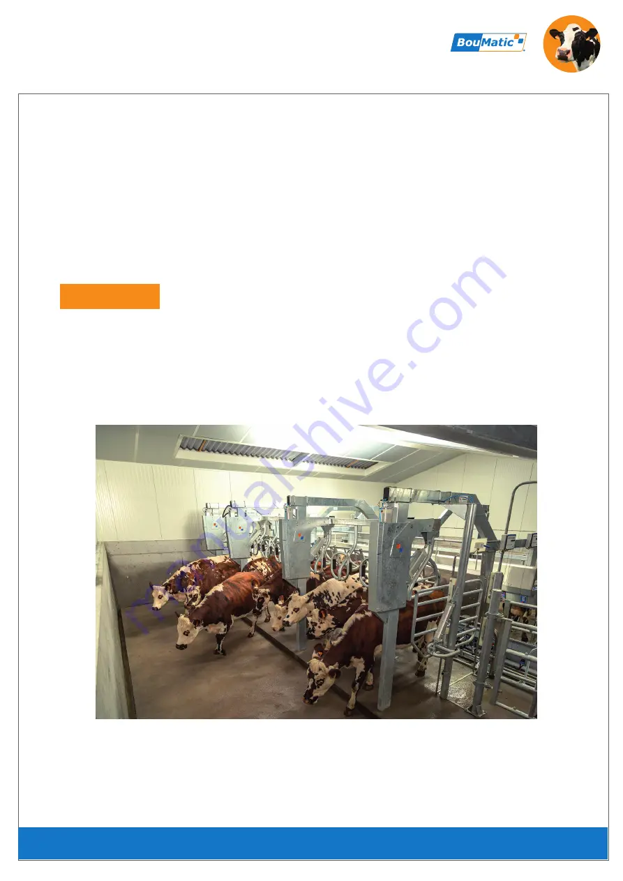
Parallel Rapid Exit Milking Parlour
www.boumatic.com
G
en
tly
, Q
uickly and Com
pl
et
el
y
™
01-2018
Страница 1: ...SmartWay 90 9e1037 Installation and Operator Manual 9e1060 Parallel Rapid Exit Milking Parlour www boumatic com G e n t l y Quickly and Com p l e t e l y 01 2018 ...
Страница 2: ...9 4 13 ASSEMBLING THE CURB 30 4 14 BITUMEN PROTECTIVE COATING 31 4 15 ASSEMBLING THE LIFTING CYLINDERS 32 4 16 ASSEMBLING THE VERTICAL GUIDE CARRIAGE 33 4 25 ASSEMBLING THE UPPER FRONT COVER 42 4 26 ASSEMBLING THE LOWER FRONT COVER 43 4 27 ASSEMBLING THE PVC DETACHER CYLINDERS 44 4 28 ASSEMBLING THE STAINLESS STEEL DETACHER CYLINDERS 45 4 29 ASSEMBLING THE COMPRESSED AIR LINE CLASSIC RUMP RAIL 46 ...
Страница 3: ...LY DIAGRAM LIFTING CYLINDERS FRONT RAIL AND ENTRANCE GATE 54 4 38 ASSEMBLING THE POSITION SENSORS 55 4 39 OPTION ASSEMBLING THE PROTECTIVE COVER 57 5 WIRING DIAGRAM 7 DECOMMISSIONING 7 1 SPECIAL PERSONNEL QUALIFICATION REQUIRED FOR DECOMMISSIONING 60 7 2 SAFETY INSTRUCTIONS FOR DECOMMISSIONING 60 7 3 SPECIAL DANGERS INVOLVED IN DECOMMISSIONING 60 7 4 FINAL DECOMMISSIONING DISPOSAL 60 5 0 WIRING DI...
Страница 4: ...res written authorization from BouMatic 1 1 MANUFACTURER S ADDRESS 1 2 CUSTOMER SERVICE If necessary please contact your nearest authorised dealer 1 3 GUIDELINES LAWS STANDARDS BouMatic A S Jernvej 2 6900 Skjern Denmark Tel 45 7694 5525 Fax 45 7526 0396 BouMatic Gascoigne Melotte Sprl Rue Jules Melotte 31 4350 Remicourt Belgium Tel 32 19 54 42 66 Fax 32 19 54 55 44 BouMatic Europe EMC compliance h...
Страница 5: ...Page 5 9e1060 1 3 1 DECLARATION OF CONFORMITY IN PREPARATION ...
Страница 6: ...h milk quality and therefore milking results When replacing parts only use genuine BouMatic spare parts Recommended settings are only valid in conjunction with genuine BouMatic products The conscientious implementation of milking routines will have a positive effect on milking results Attention Milking without milk flow overmilking must be avoided as it will very quickly have an adverse effect on ...
Страница 7: ...s maintenance and service personnel A full set of legible instructions must always be kept near the product Anyone having to work on the product must have the possibility to look into the instructions at any time The owner has to ensure that his staff receive adequate training adapted to suit the specific conditions of his facility emphasis should be placed on safety aspects Unauthorised persons e...
Страница 8: ...ating instructions of the manufacturer Observe noise protection measures Do not stand underneath suspended loads Always keep control cabinets all power supply units and electrical control units closed Access is only permitted to authorized personnel with a key or special tool Protect live and high voltage components against moisture Water jets and high pressure cleaners must NOT under any circumst...
Страница 9: ...dition special qualifications are required for the following activities Transportation Handling Maintenance Cleaning Installation Start up Service Troubleshooting Repairs Deviation from these instructions could affect product performance or create a hazardous situation Under no circumstances will BouMatic be responsible for any problems caused in whole or in part by a deviation from the procedures...
Страница 10: ...affixed to the product must be replaced immediately when illegible or lost 2 6 PACKAGING MATERIALS Packaging materials must be disposed of in accordance with applicable local regulations BouMatic equipment and components are designed exclusively for agricultural facilities mostly dairy farms This product component is designed exclusively for use during the milking process in parlours for cows or g...
Страница 11: ... and animals or for damage to Bou Matic products caused as a result of using non original parts or accessories or by incorrect settings During repair and service operations always cut the power to the control unit by turning off the switch The control unit contains 230 400 V AC circuits and may only be opened by a BouMatic installer or a qualified electrician Installation together with any repairs...
Страница 12: ...iers must be available 1 Electrical power supply 230V 50 Hz Europe 2 Pneumatic energy compressed air 8 bar constant and oil free The system is operated by a control unit installed in the milking pit so that the controlled actions can be monitored Please check the scope of delivery of the delivered goods and confirm receipt Please check the delivered goods against the order confirmation and deliver...
Страница 13: ...st have knowledge of the type of installation and possible risks The instructions in this manual must be followed BouMatic accepts no responsibility or warranty for damages resulting from improper installation and their consequential damage The following information must be observed During welding operations in particular of galvanised parts harmful gases can lead to damage to health Avoid breathi...
Страница 14: ...ls Failure to do so could result in serious permanent injury All electrically conductive system components must be connected to the building s potential equalization Ø Screw Torques of the fixing screws Nm Strength class 4 6 4 8 5 6 5 8 6 6 6 8 8 8 10 9 12 9 M4 1 12 1 50 1 40 1 87 1 68 2 25 3 00 4 21 5 06 M5 2 17 2 89 2 71 3 62 3 26 4 34 5 79 8 15 9 78 M6 3 74 4 90 4 60 6 24 5 62 7 49 9 99 14 00 1...
Страница 15: ... min 152 220 288 Calculated required air volume at 6 bar in l h at 4 passages hour 202 293 384 Milking parlour size 2x14 2x16 2x18 2x20 2x24 2x28 2x32 2x36 2X40 2X44 2X48 Number of lifting cylinders Ø 100 x 850 10 12 14 16 18 20 22 24 26 Number of index cylinders Ø 100 x 250 10 12 14 16 18 20 22 24 26 Number of entrance door cylinders Ø 63 x 400 2 2 2 2 2 2 2 2 2 Calculated required compressed air...
Страница 16: ...8 7 4 2410 94 7 2420 MAXI 95 3 1830 mini 72 776 30 5 1070 42 selon opérateur 2680 105 4 Largeur de couloir 2670 40 x nb de postes par côté 105 1 6 x nb post 2122 83 5 O 76 3 Adapted to the height of the milker min min max max Corridor width 2670 40 mm x number of milking places per side 105 1 6 x number of milking places per side ...
Страница 17: ...e postes par côté 700 29 13 x nb post 27 5 510 20 1 740 29 1 530 21 3 places 4 places 3 places Milking parlour length 740 mm x number of milking places per side 700 mm Milking parlour length 29 13 x number of milking places per side 27 5 Size Size Distribution and size of front rail elements Distribution and size of front rail elements Free area access to the control cabinet DETAIL A ...
Страница 18: ...175 BOFBN10175 1 Standpfosten SMARTWAY 90 BOSW000500 Beschreibung A DETAIL A Teilenummer 1 2 3 4 5 6 7 5 7 6 8 1 345 20 20 O 30 70 env 2 75 Avant projet 0310 SW 005 Poteaux beams DETAIL A ca 70 Pos Description Part number 1 Support post SMARTWAY 90 BOSW000500 4 Plug anchors FBN M 10x175 BOFBN10175 3 Nut H M10 4 Main cross beam right left BOSW100500 5 Rectangular U bolts 140x80 6 Self locking nut H...
Страница 19: ... Number of places x Number of places Important Check and adjust Correct height and position of the support posts Diagonal length spacing and vertical alignment of the support posts Sturdiness and stability of the support posts in the concrete Correct distribution of the support posts at a distance of 740 mm or 29 13 The support posts must be absolutely perpendicular in any vertical direction ...
Страница 20: ...f Binet Réf Boumatic A DETAIL A B DETAIL B 1 2 3 4 5 6 3 865 34 Check the parallel alignment of the entrance gates to the respective beams 4 3 ASSEMBLING THE SUPPORTING ENTRANCE GATE COMPONENTS Pos Description Part number 1 Support post entrance gate SmartWay 90 BOSW000507 2 Plug anchors FBN M 10x175 BOFBN10175 3 Flat washer M 10 4 Nut M 10 5 Rectangular U bolt 140x80 6 Self locking nut H M10 BOEC...
Страница 21: ...MARTWAY 90 C Ga BOSW000507 NĀ Désignation Réf Binet Réf Boumatic 1 9 10 2 3 4 5 7 8 11 12 13 14 15 16 17 18 19 20 6 MAX 5 bars 21 22 23 24 25 26 4 4 ASSEMBLING THE ENTRANCE GATE Pos Description Part number 1 Support post entrance gate SmartWay 90 BOSW000507 4 POM bearing BOXP710525 3 Round shaft 25 x 4 mm length 324 BOXP130535 4 Entrance gate SmartWay 90 BOSW000521 5 Screw Q M16 375 6 Self locking...
Страница 22: ...ant projet 0515 SW 026 Embout de gouttière_Panneau important bmp 2 3 1 Choose the drain side 2 of the gutter Create a recess if required 4 5 ASSEMBLING THE MANURE GUTTER ENDPIECES No Description Part Number 1 Gutter 3 stalls BOSW300584 2 Gutter endpiece drain left side 3 Gutter endpiece right side BOSW300577 BOSW300514 ...
Страница 23: ...70 1 POTENCE SIMPLE BOSW300500 NĀ Désignation Réf Binet Réf Boumatic A DETAIL A 3 1 2 4 6 ASSEMBLING THE CLASSIC CROSSBEAM for Supreme rump rail see point 4 9 No Description Part Number 1 Simple crossbeam BOSW300500 2 Screw H M10 170 3 Locknut H M10 BOECF00010 ...
Страница 24: ...OSW300507 1 GOUTTIERE 3 PLACES BOSW300514 NĀ Désignation Réf Binet Réf Boumatic 1 2 3 4 5 4 7 ASSEMBLING THE CLASSIC GUTTER No Description Part Number 1 Gutter 3 stalls BOSW300514 2 Gutter 4 stalls BOSW300507 3 Screw TRCC M8x20 stainless steel 4 Washer L 8 stainless steel 5 Nut H M8 stainless steel ...
Страница 25: ...OTENCE CLASSIQUE C Gauche BOSW300556 NĀ Désignation Réf Binet Réf Boumatic 4 6 5 1 2 3 7 7 4 8 ASSEMBLING THE CLASSIC SPLASH PANEL No Description Part Number 1 Endpiece Classic crossbeam left side BOSW300556 2 Shim for rump rail BOSW400528 3 Splash panel 3 stalls 4 Screw TRCC M8x20 stainless steel 5 Washer L 8 stainless steel 6 Nut H M8 stainless steel BOSW300542 7 Washer L 10 stainless steel ...
Страница 26: ...010 2 VIS H M10 170 1 POTENCE SUPREME BOSW400500 NĀ Désignation Réf Binet Réf Boumatic A DETAIL A 1 2 3 4 9 ASSEMBLING THE SUPREME CROSSBEAM No Description Part Number 1 Supreme crossbeam BOSW400500 2 Screw H M10 170 3 Locknut H M10 BOECF00010 ...
Страница 27: ...SW300507 1 GOUTTIERE 3 PLACES BOSW300514 NĀ Désignation Réf Binet Réf Boumatic 1 2 3 4 5 4 10 ASSEMBLING THE SUPREME GUTTER No Description Part Number 1 Gutter 3 stalls BOSW300514 2 Gutter 4 stalls BOSW300507 3 Screw TRCC M8x20 stainless steel 4 Washer L 8 stainless steel 5 Nut H M8 stainless steel ...
Страница 28: ...TE DE POTENCE SUPREME C Gauche BOSW400556 NĀ Désignation Réf Binet Réf Boumatic 3 2 4 6 5 1 4 11 ASSEMBLING THE SUPREME SPLASH PANEL No Description Part Number 1 Endpiece Supreme crossbeam left side BOSW400556 2 Shim for rump rail BOSW300542 3 Splash panel 3 stalls 4 Screw TRCC M8x20 stainless steel 5 Washer L 8 stainless steel 6 Nut H M8 stainless steel BOSW400528 ...
Страница 29: ... BOSW400731 NĀ Désignation Réf Binet Réf Boumatic A DETAIL A 1 2 3 4 1 DETAIL A Pos Description Part number 1 Detacher bracket BOSW400731 2 Screw TRCC M8x20 stainless steel 3 Flat washer L 8 stainless steel 4 Nut H M8 stainless steel 4 12 ASSEMBLING THE DETACHER BRACKETS FOR SUPREME CABINET ...
Страница 30: ...BOXP501020 1 RIVE DE QUAI INOX XP 3280 BOXP501500 NĀ Désignation Réf Binet Réf Boumatic A DETAIL A 1 2 3 4 5 4 13 ASSEMBLING THE CURB DETAIL A Pos Description Part number 1 Curb stainless steel XP 3280 BOSW400528 2 Angled rail for sealing BOSW300542 3 Screw TRCC M12x30 4 Flat washer M 12 5 Nut H M12 ...
Страница 31: ...NEUSE POT DE 1 Kg BOPBBP0001 NĀ Désignation Réf Binet Réf Boumatic A bitumen coating must be applied to all parts to be encased in concrete up to 50 mm 2 above the top edge of the finished concrete Not included in the scope of delivery please order separately 4 14 BITUMEN PROTECTIVE COATING Pos Description Part number 1 Bitumen sealing paint 1kg container BOPBBP0001 Page 31 ...
Страница 32: ...NĀ Désignation Réf Binet Réf Boumatic A DETAIL A 1 2 3 5 4 6 7 8 9 11 12 13 10 14 16 15 4 15 ASSEMBLING THE LIFTING CYLINDERS DETAIL A Pos Description Part number 1 Lifting cylinder attachment BOSW200500 2 Sleeve Ø 21 3 Length 15mm BOSW200507 3 Screw H M16 50 4 Compressed air flow regulator bracket BOSW500612 5 Self locking nut H M16 BOECF00016 6 Compressed air cylinder Ø100x850 BOSW200514 7 Flat ...
Страница 33: ...n BOSW200535 2 Führungsrolle BOSW200542 3 Laufhülse Ø 25x4 Länge 137mm BOSW200549 4 Schraube H M16 170 5 selbstsichernde Mutter H M16 BOECF00016 6 Anschlussschuh Hubzylinder BOSW200528 7 Schraube H M12 30 8 selbstsichernde Mutter H M12 BOTCD03015 9 Unterlegscheibe M20 10 Schraube H M20 70 11 selbstsichernde Mutter H M20 Pos Description Part number 1 Guide carriage BOSW200535 2 Guide roller BOSW200...
Страница 34: ... Frontgatter BOSW200577 4 Lager POM BOXP710525 5 Scheibe Z 27 BOROZ00027 6 Hülse Ø 25x4 Länge 147mm BOSW200584 7 Schraube H M16 160 8 selbstsichernde Mutter H M16 BOECF00016 9 Zylinder Ø100x250 BOSW200605 10 hintere Index Zylinderhalterung BOSW200591 11 Scheibe Pega Ø10 12 Schraube H M10x30 13 Laufhülse Ø 25x4 Länge 137mm BOSW200549 14 Schraube H M16 170 15 Gelenkkopf M20 Ø20 BORI463040 16 Scheibe...
Страница 35: ... FRONT RAIL CROSS BEAM For alignment please use the shims Pos Beschreibung Teilenummer 1 Querträger 3 Plätze linke Seite BOSW200626 2 Ausgleichsstück Querträger BOSW200654 3 Schraube H M12 30 4 selbstsichernde Mutter H M12 5 Verschlusskappe Ø 50 60 8580178 6 Lager Platzteiler Pos Description Part number 1 Front rail cross beam 3 places left side BOSW200626 2 Shim front rail BOSW200654 3 Screw H M1...
Страница 36: ... 6 7 4 19 ASSEMBLING THE DIVIDER GATES Pos Beschreibung Teilenummer 1 Platzteiler geneigt BOSW200675 2 Achse Platzteiler BOSW200682 3 Schraube CHC M8 50 4 Mutter H M8 5 Verschlusskappe Ø 40 49 8504862 6 Gummi Stopper T T M 8 x 30 x 20 BOBCM83020 7 Schraube H M8 30 Pos Description Part number 1 Divider gate slanted BOSW200675 2 Axis divider gate BOSW200682 3 Screw CHC M8 50 4 Nut H M8 5 End cap Ø 4...
Страница 37: ...E D EXTREMITE BOSW200689 NĀ Désignation Réf Binet Réf Boumatic A DETAIL A B DETAIL B 6 1 2 3 4 5 7 8 9 10 13 12 11 14 15 16 Classic version Supreme version 17 13 110 4 3 4 20 ASSEMBLING THE END BARRIER No Description Part Number 1 End barrier support tube BOSW200689 2 Clamp for end barrier support tube BOSW200696 3 Screw H M12 110 4 Locknut H M12 5 End cap Ø 40 49 8504862 6 End barrier BOSW200703 ...
Страница 38: ...egscheibe L 8 BOROL00008 4 Mutter H M8 5 Verstärkung Bodenblech BOSW400626 6 Schraube TRCC M8x20 Edelstahl 7 Unterlegscheibe L 10 Edelstahl 8 Unterlegscheibe L 8 Edelstahl 9 Mutter H M8 Edelstahl 10 Bodenblech 3 Plätze BOSW400640 11 Schraube TRCC M6x12 Edelstahl 12 Unterlegscheibe L 6 Edelstahl 13 Mutter H M6 Edelstahl Pos Description Part number 1 Main holder cabinet base plate BOSW400598 2 Screw...
Страница 39: ...ndungsabdeckung mit Bedienfeld BOSW400661 3 Verbindungsabdeckung BOSW400654 4 Schraube TRCC M6x12 Edelstahl 5 Unterlegscheibe M 6 Edelstahl 6 Mutter H M6 Edelstahl 7 Schraube BHC M6 16 8 Gehäusehalter z B für Klemmkasten BOSW500521 9 Schraube TRCC M8x20 Edelstahl 10 Unterlegscheibe L 8 Edelstahl 11 Mutter H M8 Edelstahl Pos Description Part number 1 Lower cabinet base plate BOSW400612 2 Connection...
Страница 40: ...7 NĀ Désignation Réf Binet Réf Boumatic 1 2 4 23 ASSEMBLING THE CABINET UPPER COVER Pos Beschreibung Teilenummer 1 obere Abdeckung Kabinett BOSW400717 2 Blindnieten Edelstahl A2 Ø4 8x10 Pos Description Part number 1 Top cover cabinet BOSW400717 2 Blind rivet stainless steel A2 Ø4 8x10 ...
Страница 41: ...chreibung Teilenummer 1 Abstandshalter BOSW400731 2 Schraube TRCC M8x20 Edelstahl 3 Unterlegscheibe L 8 Edelstahl 4 Mutter H M8 Edelstahl 5 Schraube BHC M8 40 Edelstahl 6 Klappenstütze für Kabinettfront oben BOSW400745 7 selbstsichernde Mutter H M8 8 Klappenstütze für Kabinettfront unten BOSW400752 Pos Description Part number 1 Cylinder bracket BOSW400731 2 Screw TRCC M8x20 stainless steel 3 Flat ...
Страница 42: ...g Teilenummer 1 obere Frontabdeckung 3 Plätze 2 untere seitliche Abdeckung linke Seite BOSW400675 3 Schraube TRCC M6x12 Edelstahl 4 Unterlegscheibe L 6 Edelstahl 5 Mutter H M6 Edelstahl 6 obere seitliche Abdeckung linke Seite BOSW400689 7 Schraube BHC M6 16 8 Blindniete Edelstahl A2 Ø4 8x10 9 obere Endabdeckung BOSW400703 Pos Description Part number 1 Upper front cover 3 places 2 Lower side cover ...
Страница 43: ...ADE BASSE DECRO 3 PLACES NĀ Désignation Réf Binet Réf Boumatic 1 4 26 ASSEMBLING THE LOWER FRONT COVER Pos Beschreibung Teilenummer 1 untere Frontabdeckung 3 Plätze Pos Description Part number 1 Lower front cover 3 places ...
Страница 44: ...osition de la griffe par rapport à la vache détermine le sens de montage du vérin 4 27 ASSEMBLING THE PVC DETACHER CYLINDERS The position of the milking unit to the udder determines the assembly direction of the cylinder ...
Страница 45: ...tage du vérin 2 3 4 4 28 ASSEMBLING THE STAINLESS STEEL DETACHER CYLINDERS Pos Beschreibung Teilenummer 1 Haltewinkel Zylinder BOSW400738 2 Schraube H M8 20 BOVTH00820 3 UnterlegscheibeL 8 4 BOROL00008 Mutter H M8 The position of the milking unit to the udder determines the assembly direction of the cylinder Pos Description Part number 1 Cylinder mounting bracket BOSW400738 2 Screw H M8 20 BOVTH00...
Страница 46: ... Rilsan Ă8 NĀ Désignation Réf Binet Réf Boumatic 21 1 2 3 4 5 6 7 8 9 10 11 13 14 1 Deburr and lubricate the tube 2 Insert and tighten the tube 30 Nm 12 16 10 14 20 19 15 18 4 3 17 13 38 1 5 4 29 ASSEMBLINGTHECOMPRESSEDAIRLINE CLASSICRUMPRAIL No Description Part Number 12 Alu tube Ø25 13 Right angle connector Ø25 14 Female tee in center Ø25 G3 8 15 Straight connector Ø8 G3 8 16 Valve 17 Screw H M6...
Страница 47: ...ilsan Ă8 NĀ Désignation Réf Binet Réf Boumatic 16 14 12 1 2 3 4 5 6 7 8 9 10 11 13 14 15 3 4 17 18 7 8 19 20 10 21 13 1 Deburr and lubricate the tube 2 Insert and tighten the tube 30 Nm 38 1 5 4 30 ASSEMBLINGTHECOMPRESSEDAIRLINE SUPREMERUMPRAIL No Description Part Number 1 Mounting bracket 2 Self tapping screw THZ 4 8x16 3 Clamp alu tube Ø25 4 Shim for tube clamp 5 Screw H M6 40 6 Filter regulator...
Страница 48: ...ET AUTOMATE BOSW500500 1 COFFRET AUTOMATE BOSW500507 NĀ Désignation Réf Binet Réf Boumatic 2 1 3 4 5 6 4 31 ASSEMBLING THE CONTROL CABINET No Description Référence 1 Control cabinet BOSW500507 2 Control cabinet mounting bracket BOSW500500 3 Screw H M8 30 4 Washer L 8 5 Nut H M8 BOROL00008 6 Locknut H M10 BOECF00010 ...
Страница 49: ...nox 1 COFFRET DE COMMANDE A BOUTONS BOSW500528 NĀ Désignation Réf Binet Réf Boumatic 1 2 3 4 5 6 7 8 9 3 4 32 ASSEMBLING THE CONTROL PANEL ON CLASSIC RUMP RAIL No Description Part Number 1 Control panel 2 Screw CS M4 12 stainless steel BOSW500528 3 Nut H M4 stainless steel 4 Junction box bracket 5 Screw H M8 16 6 Washer L 8 BOROL00008 7 Nut H M8 8 Junction box 9 Upper end cover BOSW500528 BOSW5005...
Страница 50: ...E DECRO SUPPORT COMMANDE BOSW400661 NĀ Désignation Réf Binet Réf Boumatic 1 2 3 4 5 6 7 8 9 10 5 4 33 ASSEMBLING THE CONTROL PANEL ON SUPREME RUMP RAIL No Description Part Number 1 Detacher control panel junction 2 Control panel BOSW400661 3 Control panel holder 4 Screw CS M4 12 stainless steel 5 Nut H M4 stainless steel 6 Screw BHC M6 16 7 Nut H M6 stainless steel 8 Junction box bracket 9 Junctio...
Страница 51: ...5 3 CF 24VDC BOCM080560 8585714 1 SUPPORT DISTRI ET BRAS D ALIMENTATION NĀ Désignation Réf Binet Réf Boumatic A DETAIL A 5 1 2 3 4 6 7 8 4 34 ASSEMBLING THE SUPPLY ARM No Description Part Number 1 Supply arm gate valve bracket 2 Gate valve 551 5 3 CF 24VDC 3 Screw CHC M5 35 4 Nut H M5 5 Supply arm 6 Screw H M8 20 8585714 7 Locknut H M8 8 Spiral cable wrap Ø21 27 BOVTH00820 ...
Страница 52: ...e O 8 O 25 O 8 B1 B2 A 220V supply O 4 V3 cylinders Ø100x850 V2 cylinders Ø100x250 V1 cylinder Ø63x400 V2 cylinders Ø100x250 O 8 O 8 fi l 2 x 0 5 fil 2x0 5 fil 2x 0 5 fi l 2 x 0 5 O 4 5 bars O 8 O 8 O 4 5 bars O 8 O 8 4 35 NETWORK ASSEMBLY BY PARLOUR SIDE ...
Страница 53: ...M080540 8585709 9 REGLEUR DE DEBIT G3 8 NĀ Désignation Réf Binet Réf Boumatic Avant projet 0515 SW 145 Alimentation indexation lice avant_Panneau danger général bmp 12 14 1 2 3 4 5 6 7 8 9 10 11 13 14 15 12 V2 cylinders Ø100x250 MAX 5 bars 4 36AIR SUPPLY DIAGRAM FRONT RAIL INDEXATION No Description Part Number 1 Supply arm gate valve bracket 2 Gate valve 551 5 3 CF 24VDC 3 Elbow fitting Ø8 G1 4 4 ...
Страница 54: ...100x850 V1 cylinders Ø63x400 D1 in cabinet O 8 O 8 V1 V1 Supply diagram front rail lift cylinder Supply diagram entrance gate cylinder O 25 O 8 O 4 190 Q5 A2 S 4 37 AIR SUPPLY DIAGRAM LIFTING CYLINDERS FRONT RAIL AND ENTRANCE GATE ...
Страница 55: ...1 Vérin Ă100x850 BOSW200514 NĀ Désignation Réf Binet Réf Boumatic A DETAIL A B DETAIL B 3 1 2 B1 B2 A 95 3 7 43 1 7 43 1 7 4 38 ASSEMBLING THE POSITION SENSORS No Description Part Number 1 Cylinder Ø100x850 BOSW200605 2 Cylinder Ø100x250 3 Sensor ILS BOSW500535 BOSW200514 ...
Страница 56: ...ned situation of the moving elements thus the position of sensor B1 corresponds to the rail in high position maximum lifting the position of sensor B2 corresponds to the rail in low position the position of sensor A corresponds to the indexation of the front rail Dimensions shown on the drawings are indicative only Precise adjustments may be required at start up of the installation ...
Страница 57: ...t Réf Boumatic 1 4 2 3 4 39 OPTION ASSEMBLING THE PROTECTIVE COVER Pos Beschreibung Teilenummer 1 Schutzabdeckung BOSW200556 2 Käfigmutter mit Clips M 8 6 BOROL00008 3 Unterlegscheibe L 8 4 Schraube H M8 20 BOVTH00820 Pos Description Part number 1 Protective cover BOSW200556 2 Cage nut with clips M 8 6 3 Flat washer L 8 BOROL00008 4 Screw H M8 20 BOVTH00820 ...
Страница 58: ...Page 58 9e1060 5 ELECTRIC SCHÉMA 5 WIRING DIAGRAM ...
Страница 59: ...Page 59 9e1060 6 REPLACEMENT AND SPARE PARTS Please refer to the relevant pages in chapter 4 Installation for the corresponding part numbers for defective replacement or spare parts ...
Страница 60: ... through in the order specified First of all make the operating area for decommissioning completely safe Make sure that operating supplies are disposed of without harming the environment Also read the chapter on Safety 7 3 SPECIAL DANGERS INVOLVED IN DECOMMISSIONING Components which have not been removed correctly may fall off or twist There is a risk of injury from open components tools with shar...
Страница 61: ...19 54 42 66 F 32 0 19 54 55 44 Denmark Jernvej 2 6900 Skjern T 45 7694 5525 F 45 7526 0396 Wisconsin USA PO Box 8050 Madison WI 53708 T 1 608 222 3484 F 1 608 222 9314 Texas USA 15180 Nautique Way Houston TX 77047 T 1 832 786 7554 F 1 832 786 4665 The Netherlands Transportweg 6 8304 AX Emmeloord T 31 0 527 820 110 F 31 0 527 788 599 Belgium Rue Jules Mélotte 31 4350 Remicourt T 32 0 19 54 42 66 F ...