background image

6720220330  Revised 05-12

9

SEQUENCE  OF  OPERATION-TWO STAGE UNITS:

(Figure #14 Wire Schematic)

COOLING  MODE:

Energizing  the  “O”  terminal  energizes  the  unit  reversing
valve  in  the  cooling  mode.  The  fan  motor  starts  when  the
“G” terminal is energized. Note that the fan motor will take
30  seconds  to  ramp  up  to  operating  speed  and  will  run  at
fan  only  rated  air  flow  as  long  as  there  is  no  call  for
compressor or heater operation.

When  the  thermostat  calls  for  first  stage  cooling  (Y1)  the
loop pump or solenoid valve is energized and the first stage
of  compressor  capacity  starts.  The  fan  ramps  up  to  first
stage cooling air flow in 30 seconds.

When the thermostat calls for second stage cooling (Y2) the
second  stage  (or  full  compressor  capacity)  is  initiated.  The
fan ramps up to full cooling air flow.

Once  the  thermostat  is  satisfied,  the  compressor  shuts
down  accordingly  and  the  fan  ramps  down  to  either  fan
only mode or off over a span of 30 seconds.

Note  that  a  fault  condition  initiating  a  lockout  will  de-
energize  the  compressor  irrespective  of  which  stage  is
engaged.

HEATING  MODE:

The  first  two  stages  of  heating  (Y1  &  Y2)  operate  in  the
same  manner  as  cooling,  but  with  the  reversing  valve  de-
energized.  On  a  call  for  auxiliary  heat  (W1),  the  fan  ramps
up  to  auxiliary  heat  air  flow  immediately  and  the  electric
heater package is energized along with the compressor. As
the thermostat is satisfied, the heaters will shut off as soon
as W1 is de-energized, and the compressors will remain on
until  the  thermostat  stages  are  satisfied.  Note  that  if  the
unit  compressor  lock  out  for  any  reason  at  this  time,  the
electric heaters will continue to function normally.

Once  the  thermostat  is  satisfied,  the  compressor  shuts
down and the fan ramps down either fan only mode or off
over  a  span  of  30  seconds.  If  emergency  heat  (W2/EM)  is
called for, the fan will ramp up to emergency heat air flow
immediately  and  the  heater  package  will  energize  in
emergency  heat  mode,  all  heater  elements  coming  on.  On
shut  down  the  fan  will  ramp  down  over  a  period  of  30
seconds.

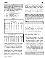
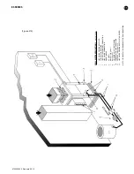
WELL WATER SYSTEMS:

(Figure #10)

In  well  water  applications  water  pressure  must  always  be
maintained  in  the  heat  exchanger.  This  can  be
accomplished  with  either  control  valve  or  a  bladder  type
expansion  tank.  When  using  a  single  water  well  to  supply
both  domestic  water  and  the  heat  pump  care  must  be
taken to insure that the well can provide sufficient flow for
both.  In  well  water  applications  a  slow  closing  solenoid
valve must be used to prevent water hammer.

Solenoid  valves  should  be  connected  across  Y1  and  C1  on
the interface board for all. Make sure that the VA draw of the

valve does not exceed the contact rating of the thermostat.

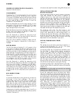
INSTALLATION OF  PRESSURE
REGULATING VALVES:

Pressure regulating valves are used to increase or decrease
water  flow  through  the  heat  pump  in  response  to
refrigerant  pressure.  In  some  cases  more  water  may  be
required  in  heating  than  in  cooling,  or  vice  versa.  With  the
Envirosaver  heat  pumps  these  valves  are  not  required.
However, if installed, a pair of valves are required for proper
operation, one valve for cooling (direct acting) and another
valve  for  heating  (indirect  acting).  A  refrigerant  tap  is
provided  in  the  refrigerant  line  located  between  the
reversing valve and the water-to-refrigerant heat exchanger
for proper monitoring of the refrigerant pressures.

The  discharge  water  from  the  heat  pump  is  not
contaminated  in  any  manner  and  can  be  disposed  of  in
various  ways  depending  on  local  building  codes  (i.e.
discharge well, dry well, storm sewer, drain field, stream or
pond,  etc.)  Most  local  codes  forbid  the  use  of  a  sanitary
sewer  for  disposal.  Consult  your  local  building  and  zoning
department to insure compliance in your area.

COOLING  TOWER/BOILER SYSTEMS:

(Figure #11)

The  cooling  tower  and  boiler  water  loop  temperature  is
usually  maintained  between  50˚  F  to  100  ˚  F  to  assure
adequate cooling and heating performance.

In the cooling mode, heat is rejected from the FHP unit into
the  water  loop.  A  cooling  tower  provides  evaporative
cooling  to  the  loop  water  thus  maintaining  a  constant
supply  temperature  to  the  unit.  When  utilizing  open
cooling  towers,  chemical  water  treatment  is  mandatory  to
ensure  the  water  is  free  from  corrosive  elements.  A
secondary  heat  exchanger  (plate  frame)  between  the  unit
and  the  open  cooling  tower  may  also  be  used.  It  is
imperative  that  all  air  be  eliminated  from  the  closed  loop
side of the heat exchanger to insure against fouling.

In the heating mode, heat is absorbed from the water loop.
A boiler can be utilized to maintain the loop at the desired
temperature.

CAUTION:

Water piping exposed to extreme low ambient

temperatures is subject to freezing.

Consult  the  specification  sheets  for  piping  sizes.  Teflon
tape sealer should be used when connecting to the unit to
insure  against  leaks  and  possible  heat  exchanger  fouling.
Do not overtighten the connections. Flexible hoses should
be  used  between  the  unit  and  the  rigid  system  to  avoid
possible  vibration.  Ball  valves  should  be  installed  in  the
supply  and  return  lines  for  unit  isolation  and  unit  water
flow 

balancing. 

Pressure/temperature 

ports 

are

recommended  in  both  supply  and  return  lines  for  system
flow  balancing.  Water  flow  can  be  accurately  set  by
measuring  the  water-to-refrigerant  heat  exchangers  water
side  pressure  drop.  See  specification  sheets  for  water  flow
vs. pressure drop information.

ES SERIES

Содержание FHP ES Series

Страница 1: ...ssure Regulating Valves 9 Cooling Tower Boiler Application 9 Earth Coupled Systems 10 System Checkout 10 Unit Start Up 10 Maintenance 10 Wiring Diagrams 14 Trouble Shooting 16 Unit Check Out 17 Operating Pressures Temperatures 18 MODEL NOMENCLATURE SERIES ES ENVIROSAVER AU AQUARIUS NOMINAL CAPACITY VOLTAGE DESIGNATION 1 208 1 60 230 1 60 3 208 3 60 230 3 60 SINGLE STEP ONLY CABINET CONFIGURATION V...

Страница 2: ...r maintenance operations on the system turn off main power to the unit Electrical shock could cause personal injury or death When working on equipment always observe precautions described in the literature tags and labels attached to the unit Follow all safety codes Wear safety glasses and work gloves Use a quenching cloth for brazing and place a fire extinguisher close to the work area LOCATION L...

Страница 3: ... the installation should be designed using current ASHRAE procedures for duct sizing If the unit is to be connected to existing ductwork a check should be made to assure that the duct system has the capacity to handle the air required for the unit application If the duct system is too small larger ductwork should be installed Check for existing leaks and repair The duct system and all diffusers sh...

Страница 4: ...r and control circuit Refer to the ELECTRIC HEATER PACKAGE OPTION section for wiring instructions minimum circuit ampacities and maximum fuse breaker sizing ECM INTERFACE BOARD THERMOSTAT CONNECTIONS Thermostat wiring is connected to the 10 pin screw type terminal block on the lower center portion of the ECM Interface Board In addition to providing a connecting point for thermostat wiring the inte...

Страница 5: ...proper jumper placement NOTE Always disconnect power before changing jumper positions on the interface board and reset the unit afterward To the left of the red and green status LED s is a row of 1 4 male quick connects These are used to pass thermostat inputs on to the rest of the control circuit Remember to always turn off unit power at the circuit breaker before attaching or disconnecting any w...

Страница 6: ...LINKS Low pressure lockout THREE BLINKS Freeze sensor lockout FOUR BLINKS Condensate overflow FIVE BLINKS Brownout Conditions The fault pulse code may be sent to the ALR fault terminal by placing the Alarm Output pin in the pulse position The pulse signal may be sent to a thermostat with a fault indication LED 24v and will display the fault code on the thermostat FREEZE SENSOR Optional freeze prot...

Страница 7: ...ITIAL POWER UP T ASC OR RS SEC TIME 30 SEC TIME 120 SEC COUNT 2 Start Timer Start Timer CC Output On CC Output Off Blink Code On Status LED Report Alarm Fault Hard Lockout ALR Output On Pulse Blink Code On Status LED Soft Lockout Record Alarm Start Counter If Applicable Start Anti Short Cycle Start Random Start Up Lockout Can Be Set To 4 Via Dip Switch Power Switchs Sensor Status Check 7 ...

Страница 8: ...he case of unit compressor and or compressor power supply failure See HP Series Heater Kit Instructions for field installations Each ES Series model has a number of heater sizes available Refer to Figure 9 for heater package compatibility with specific ES Series units models nomenclature and electrical data SEQUENCE OF OPERATION SINGLE STAGE UNITS Figure 13 Wire Schematic COOLING MODE Energizing t...

Страница 9: ...ake sure that the VA draw of the valve does not exceed the contact rating of the thermostat INSTALLATION OF PRESSURE REGULATING VALVES Pressure regulating valves are used to increase or decrease water flow through the heat pump in response to refrigerant pressure In some cases more water may be required in heating than in cooling or vice versa With the Envirosaver heat pumps these valves are not r...

Страница 10: ...stem switch to the OFF position The unit should stop running and the reversing valve should deenergize 6 Leave the unit off for approximately 5 minutes to allow for system equalization 7 Turn the thermostat to the lowest setting 8 Set the thermostat switch to HEAT 9 Increase the thermostat setting approximately 5 degrees above the room temperature 10 Verify the heat pump is operating in the heatin...

Страница 11: ...ONNECTION 3 LOW VOLTAGE CONTROL CONNECTION 4 LINE VOLTAGE CONNECTION 5 VIBRATION PAD 6 P T PORTS 7 HOSE KITS Optional 8 BALL VALVES 9 SOLENOID VALVE SLOW CLOSING 10 CONDENSATE DRAIN CONNECTION 11 PRESSURE TANK Optional 12 LINE VOLTAGE DISCONNECT ELECTRIC HEATER NOTE SEE FIGURE 3 FOR CONDENSATE DRAIN CONNECTION ES SERIES ...

Страница 12: ...E CONTROL CONNECTION 3 P T PLUGS Optional 4 HOSE KITS Optional 5 BALL VALVES 6 SUPPLY AND RETURN LINES OF CENTRAL SYSTEM 7 FLEX DUCT CONNECTION 8 HANGING BRACKETS ASSEMBLY 9 THREADED ROD 10 HANGING BRACKET ASSEMBLY ES048 and up 930 006 NOTE SEE FIGURE 3 FOR CONDENSATE DRAIN CONNECTION Figure 11 ES SERIES ...

Страница 13: ...TROL CONNECTION 4 LINE VOLTAGE CONNECTION UNIT 5 P T PORTS 6 VIBRATION PAD 7 CONDENSATE DRAIN 8 GROUND LOOP CONNECTION KIT 555 000 001 9 GROUND LOOP PUMPING PACKAGE GL001 1 or 002 1 10 POLYETHELENE WITH INSULATION 11 LINE VOLTAGE DISCONNECT ELECTRIC HEATER NOTE SEE FIGURE 3 FOR CONDENSATE DRAIN CONNECTION Figure 12 ES SERIES ...

Страница 14: ...6720220330 Revised 05 12 14 ES SERIES Figure 13 ...

Страница 15: ...6720220330 Revised 05 12 15 Figure 14 ES SERIES ...

Страница 16: ...arge The unit is overcharged with refrigerant Reclaim refrigerant evacuate and recharge with factory recommended charge High pressure Check for defective or improperly calibrated high pressure switch UNIT OFF ON LOW PRESSURE CONTROL Suction pressure too low In COOLING mode Lack of or inadequate air flow Entering air temperature too cold Blower inoperative clogged filter or restrictions in ductwork...

Страница 17: ...__ Entering Leaving Fluid Temp _______________ _______________ _______________ _______________ Compressor Volts Amps _______________ _______________ _______________ _______________ Blower Motor Volts Amps _______________ _______________ _______________ _______________ Fluid Flow gpm _______________________________ _______________________________ Fluid Side Pressure Drop ___________________________...

Страница 18: ... 7 9 28 33 2 147 179 357 437 13 16 16 18 149 181 345 422 12 14 29 35 4 141 172 335 411 7 9 17 20 156 190 352 432 8 10 31 37 2 151 185 402 492 13 15 15 18 4 146 177 378 459 7 9 16 19 4 76 92 242 297 3 4 13 14 6 80 97 249 304 2 3 13 15 4 125 151 180 221 14 18 19 22 89 108 255 312 4 5 15 17 6 120 146 169 207 8 10 20 23 93 113 261 320 3 3 16 18 4 134 163 211 258 14 18 18 21 106 118 267 327 5 6 17 19 6...

Страница 19: ...9 426 14 17 16 20 149 182 319 390 8 10 25 30 9 0 144 176 328 401 8 9 17 21 156 191 327 400 6 7 26 32 4 5 155 189 392 480 13 16 16 19 9 0 149 182 369 451 8 9 17 21 4 0 64 78 248 303 5 6 15 18 6 0 67 82 254 311 3 4 16 19 4 0 109 134 183 224 18 22 19 23 75 91 261 319 6 8 17 21 6 0 105 128 172 210 10 12 20 25 79 96 267 327 4 5 18 23 4 0 118 144 214 261 18 22 19 23 142 173 273 334 8 10 20 24 6 0 113 13...

Страница 20: ...16 20 18 22 143 175 385 471 12 15 33 41 7 0 122 149 321 392 11 13 18 22 152 186 393 480 9 11 35 43 5 0 128 157 378 462 16 19 17 21 7 0 125 152 353 432 11 13 18 22 7 0 68 84 256 313 5 7 19 23 14 0 73 89 261 319 4 5 20 25 7 0 117 143 182 222 15 19 21 26 81 99 277 339 7 8 22 26 14 0 114 139 170 208 11 14 22 27 86 105 283 346 5 6 23 28 7 0 120 147 215 263 15 18 20 25 93 114 299 365 8 9 24 29 14 0 117 ...

Страница 21: ...64 351 429 13 16 18 22 146 178 388 474 12 15 33 41 16 0 131 159 329 401 10 12 19 23 155 189 396 483 9 11 35 43 10 0 137 167 385 469 12 15 17 21 16 0 134 163 360 439 9 11 18 22 3 0 68 83 243 297 6 7 14 17 5 0 76 92 253 309 3 4 15 18 3 0 133 162 171 209 17 21 18 22 83 101 255 312 7 9 16 20 5 0 128 156 155 190 10 13 19 23 92 113 266 325 4 5 17 21 3 0 135 165 205 251 17 20 17 21 98 119 268 327 9 11 19...

Страница 22: ...13 16 16 19 147 179 347 424 12 14 29 36 7 5 138 169 338 414 7 9 17 21 154 188 355 434 8 10 31 38 3 5 149 182 405 495 13 15 15 19 7 5 143 174 381 465 7 9 16 20 4 5 74 90 244 299 3 4 13 15 9 0 78 95 251 306 2 3 13 16 4 5 122 149 183 224 14 18 19 23 87 106 257 314 4 5 15 18 9 0 117 143 172 210 8 10 20 24 91 111 263 322 3 3 16 19 4 5 131 160 214 261 14 18 18 22 164 201 269 329 5 6 17 20 9 0 126 154 20...

Страница 23: ...170 347 424 11 14 17 21 151 185 371 453 10 12 32 39 6 0 149 183 415 508 19 24 16 19 10 0 143 175 391 477 11 14 17 21 8 0 68 84 256 313 5 7 19 23 12 0 73 89 261 319 4 5 20 25 8 0 113 138 172 210 18 22 19 23 81 99 277 339 7 8 22 26 12 0 110 134 161 196 12 14 20 24 86 105 283 346 5 6 23 28 8 0 116 142 206 252 17 21 19 23 93 114 299 365 8 9 24 29 12 0 112 137 193 236 12 14 19 24 99 121 305 373 6 7 25 ...

Страница 24: ...6720220330 Revised 05 12 601 N W 65th Court Ft Lauderdale FL 33309 Phone 954 776 5471 Fax 954 776 5529 www boschtaxcredit com www fhp mfg com ...

Отзывы: