


ACS 561 Service Manual
Robert Bosch GmbH
SP00D00517
2018-07-11
69
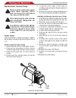
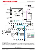
Plumbing and Mechanical
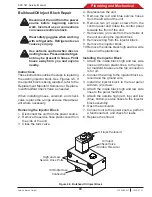
Bulkhead/Oil Inject Block Repair
Disconnect the unit from the power
source before beginning service
work. Incorrect use or connections
can cause electrical shock.
Wear safety goggles when working
with refrigerants. Refrigerants can
cause eye injury.
Use extreme caution when discon-
necting hoses. Pressurized refriger-
ant may be present in hoses. Point
hoses away from you and anyone
nearby.
Instructions
These instructions outline the steps to replacing
the existing injector block. See Figures 4-5. If
the injector block is being repaired, refer to the
Replacement Manifold Solenoid or Replace-
ment Manifold Check Valve as needed.
When installing hoses, solenoid, and check
valve, replace the o-rings and use thread seal-
ant where necessary.
Removing the Injector Block
1. Disconnect the unit from the power source.
2. Remove the service hose plastic cover from
the side of the unit.
3. Close the tank valve.
4. Depressurize the unit.
5. Remove the red and blue service hoses
from the left side of the unit.
6. Remove two (2) upper screws from the
control panel and rotate the control panel
towards the front of the unit.
7. Remove two (2) rivets from the left side of
the unit securing the injector block.
8. Remove wiring from the injector block.
9. Remove the injector block.
10. Remove the inside black high and low side
lines and the plastic line.
Installing the Injector Block
1. Attach the inside black high and low side
lines and the two plastic lines, to the injec-
tor manifold. Make sure the top connection
is for oil.
2. Connect the wiring to the injector block so-
lenoid and the ground wire.
3. Install the injector block to the rear panel
with two (2) screws.
4. Attach the inside black high and low side
lines to the panel manifold.
5. Attach the outside high (red, top) and low
(blue, bottom) service hoses to the injector
block assembly.
6. Open the tank valve.
7. Connect unit to the power source, perform
a functional test, and check for leaks.
8. Replace the shroud.
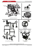
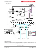
Figure 4-5. Bulkhead Oil Inject Block
Oil Inject Solenoid
Oil Inject
Check Valve
(Hidden, this side.)
High and Low
Service Hose Ports
Oil Bottle Hose
Connection
Содержание ACS 561
Страница 1: ...ACS 561 en Repair instruction A C Service Unit ...
Страница 95: ......


