ACS 561 Service Manual
Robert Bosch GmbH
SP00D00517
2018-07-11
34
Diagnostics and Testing
5. Verify the low-side (gauge), tank, and accu-
mulator transducer pressures are providing
logical readings. A transducer reading of
1046 mBar (31 in-Hg) vacuum means the
transducer is defective.
6. Compare the accumulator transducer
reading with the manual gauge reading at
the accumulator service port. Replace the
transducer if its reading doesn’t match the
calibrated test gauge.
Verify replacement transducer reads
zero before installing it into the machine
by connecting it to the wire harness and
checking the reading in the “display
pressures” screen in the service menu.
Check Accumulator Pressure Transducer
and Solenoids
1. Enter the Service Menu and turn on DIS-
PLAY ACC PRESSURE.
2. Fill the service hoses and then recover.
3. The clearing must stop at -0.4 bar.
4. Compare accumulator pressure reading on
display with manual gauge.
5. If this is a new unit and the accumulator
pressure is higher than 690 mBar (10 psi),
the accumulator shell and look for loose nuts
on the copper coil. Install accumulator shell
when inspection/repair is complete.
6. If accumulator pressure is between 69 mBar
and 690 mBar (1 psi and 10 psi), open the
compressor oil return solenoid and look for
debris.
7. If accumulator pressure is between 0 Bar (0
psi) and 270 mBar (8 in-Hg), pull one wire
off the compressor oil return solenoid (S7).
• If unit completes recovery with one wire
off the solenoid, the discharge solenoid
may be leaking by the plunger. Replace
it and recover hoses again.
• If unit still does not complete recovery,
charge solenoid (S3) might be leaking past
the plunger. Close the tank liquid valve,
bleed the liquid line, then replace the
charge solenoid (S3). Run all tests again.
Inspect the Check Valves
1. Close all tank valves.
2. Relieve pressure on the vapor hose at the
tank.
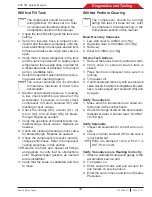
Will Not Recover
The compressor should be running
during this test. If it does not run, refer
to compressor troubleshooting in the
Compressor section of this manual.
1. Verify there is pressure reading on the
gauges.
• If pressure is present, the service hoses
are connected correctly.
• If pressure is absent, the service hoses
are connected improperly or there is a
restriction. Clear and reconnect service
hoses.
2. Display the accumulator pressure.
• If there is no pressure, inspect inlet
valves, recover solenoid and check
valves.
• If pressure seems normal at the
accumulator, inspect oil return solenoid,
compressor, and charge solenoid.
The recover solenoid is controlled to maintain
35 psi (max) in the accumulator.
3. Check the clearing discharge check valve
for bleed-through. Repair as needed.
4. Verify operation of the recover and normal/
discharge check valves. Replace as needed.
5. Check the compressor for suction and
discharge performance.
6. Remove the filter and inspect all fittings
and gaskets to verify that no obstructions
exist. Replace/repair gaskets as needed
and reinstall filter.
3. Remove both the normal discharge and
clearing discharge check valves.
4. Inspect them for debris and cut o-rings.
5. Inspect and test check valve function by
pushing the check valve plunger completely
open. Verify it moves smoothly and returns
correctly to the sealing position.
6. Replace or reinstall the check valves based
on what was replaced.
7. Tighten vapor hose.
8. Open tank valve and verify unit operation if
a bad check valve was replaced.
If unit continues to fail, test compressor per in-
structions. If failure persists, check vapor hose
for free flow, then call the Tech Line. Go into
the service menu and turn off DISPLAY ACC
PRESSURE when repair is complete.
Содержание ACS 561
Страница 1: ...ACS 561 en Repair instruction A C Service Unit ...
Страница 95: ......

