ACS 561 Service Manual
Robert Bosch GmbH
SP00D00517
2018-07-11
27
Diagnostics and Testing
Output Test
The Output Test checks the electrical outputs
from the power board and wiring harnesses to
the various solenoids, fan, vacuum pump, and
compressor. This test is useful as a trouble-
shooting method to determine if a device is
operating properly or not.
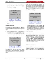
1. From the Service Menu, scroll to Output
Test.
2. Press Select (F1). The following displays:
The placeholder “X” indicates the state of the
output device. A “1” or “0” indicates whether
the device is ON or OFF. A list of the tests is
provided in the table below:
OUTPUT TEST
S1
Recover Solenoid
S2
Vacuum Solenoid
S3
Charge Solenoid
S4
ISV Liquid Solenoid
S5
Oil Inject Solenoid
S6
Oil Drain Solenoid
S7
Oil Return Solenoid
S8
Unused
S9
Unused
S10
Unused
S11
Unused
OUTPUT TEST
FAN
Fan
PUMP
Vacuum Pump
COMP
Compressor
Beacon
Unused
Beeper
Beeper
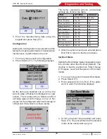
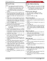
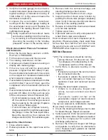
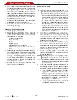
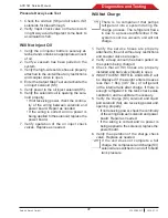
3. As the tests are highlighted, press On/Off.
The state will change from “0” to “1”. There
should be a “click” heard as the solenoids
are energized, the motors of the fan, vacu-
um pump, and compressor should start, the
beacon, if installed will flash once, and the
beeper will sound.
4. When the test is complete, press Exit (F2)
to return to the Service Menu.
Input Test
The Input Test presents a present value of the
many parameters the control board processes
to correctly operate the unit. The parameters
shown in this test are observable only and can-
not be changed or deleted. They can be used
to indicate whether or not a parameter is within
the required limits for proper unit operation.
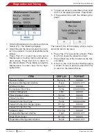
1. From the Service Menu, scroll to Input Test.
2. Press Select (F1). The following displays:
The placeholders “X” and “Y” represent actual
values seen during this test. A list of the param-
eters and what the values represent follows:
Содержание ACS 561
Страница 1: ...ACS 561 en Repair instruction A C Service Unit ...
Страница 95: ......

