background image

724-746-5500   |   blackbox.com 

Page 25

Chapter 5: Serial Configuration

Table 5-1. Topology file options.

Number

Option

Function

1

Open Existing Topology

Open pre-stored topology file

2

Save Current Topology

Allow users to save current topology file in the location where the software is 
installed.

3

Save Current Topology As… Allow users to save current topology file in the requested location.

4

Create New Device File

(reserved)

5

Exit

Exit the system

Actions:

 Detect all devices or connect the selected device. When you check “Detect All Devices,” the  dialog box in Figure 5-8 

will appear. This means the system successfully detects the device.

View:

 Show or hide the (Icon) Toolbar/Status Bar (on the bottom of the window).

Tools:

a. Communication Port: set up COM Port and Baud Rate or set up TCP/IP address for the device.

b. Language: “English” and “Traditional Chinese” are available.

Help:

 Show the software version and copyright information.

3. GUI Function Description

Figure 5-9. GUI functions.

The following describes the overall functions. Four sections are included: Info, Setting, Upgrade, EDID, and Tools.

• Info: Show information and features.

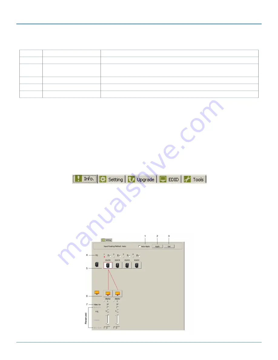
•  Setting: In this section, users can set up port connection, enable or disable audio/video separately, set scan time rate, etc. By 

default, the system will automatically apply source 1 routing to all displays as shown below.

Figure 5-10. User controls on the unit.

Содержание VSW-HDMI2X2-4K

Страница 1: ...de U S call 724 746 5500 FREE technical support 24 hours a day 7 days a week Call 724 746 5500 or fax 724 746 0746 www blackbox com info blackbox com Customer Support Information Switch one of two or...

Страница 2: ...Talk to Black Box You ll be live with one of our technical experts in less than 60 seconds Trademarks Used in this Manual Black Box and the Double Diamond logo are registered trademarks of BB Technol...

Страница 3: ...en the equipment is operated in a commercial environment Operation of this equipment in a residential area is likely to cause interference in which case the user at his own expense will be required to...

Страница 4: ...n el flujo de aire por los orificios de ventilaci n 10 El equipo el ctrico deber ser situado fuera del alcance de fuentes de calor como radiadores registros de calor estufas u otros aparatos incluyend...

Страница 5: ...W HDMI4X2 4K 11 3 Installation 14 3 1 Device Connection 14 3 2 Connection Pattern 14 4 Operation 15 4 1 LED Indicator 15 4 2 Push Button Control 16 4 2 1 A V Source Selection 16 4 2 2 EDID Setting 17...

Страница 6: ...ut VSW HDMI2X2 4K 2 HDMI female VSW HDMI4X2 4K 4 HDMI female Output 2 HDMI female Serial Port VSW HDMI2X2 4K or VSW HDMI4X2 4K 1 RJ 12 female IR Controls VSW HDMI2X2 4K or VSW HDMI4X2 4K Yes User Cont...

Страница 7: ...ve technology designed to avoid unnecessary flicker when adding system instruments Optimizes signals by choosing the best output setting from the available alternatives Complies with HDCP standard Com...

Страница 8: ...ol 1 RJ 12 to RS 232 Converter for serial RS 232 control To download this user manual from the Black Box Web site follow the instructions below 1 Go to www blackbox com 2 Enter the part number in the...

Страница 9: ...apter 2 Overview 2 4 Hardware Description 2 4 1 VSW HDMI2X2 4K 14 16 Figure 2 1 VSW HDMI2X2 4K front panel 8 7 6 5 4 3 2 1 Figure 2 2 VSW HDMI2X2 4K back panel 9 10 11 12 14 1 2 3 4 5 6 7 8 16 15 13 F...

Страница 10: ...udio Video EDID Setting 6 EDID Copy button Copy the monitor s EDID 7 Serial port Port for serial control using RJ 11 connector 8 Power supply Apply power to the unit 9 10 Video Output 1 Status LED Lig...

Страница 11: ...Chapter 2 Overview 2 4 2 VSW HDMI4X2 4K 18 20 22 Figure 2 4 VSW HDMI4X2 4K front panel 9 8 7 6 5 4 3 2 1 Figure 2 5 VSW HDMI4X2 4K back panel 10 11 12 13 14 15 16 17 20 1 2 3 4 5 6 7 8 9 22 18 21 19 F...

Страница 12: ...Switch Configure Audio Video EDID Setting 7 EDID Copy button Copy the monitor s EDID 8 Serial port Port for serial control using RJ 11 connector 9 Power supply Apply power to the unit 10 11 12 13 Vid...

Страница 13: ...ed Autosensing switch functions Number in Figure 2 8 Setting Description 1 Switch Press BTNA or BTNB on the top panel to select source in sequence 2 Auto sensing System will automatically select the l...

Страница 14: ...ctor or TV and then power on the source device s 5 If necessary apply EDID Copy process see EDID Setting section NOTE When each video source is powered on make sure it has a display pointing to it for...

Страница 15: ...ideo Output Status LED 1 2 3 and 4 Video Input Status LED 1 2 3 and 4 IR sensor Figure 4 2 LEDs on the top panel of the 4 x 2 switch 4 1 LED Indicator Switch Mode Switch EGO Auto EGO Priority S1 S4 LE...

Страница 16: ...monitor HDCP are not matched Video Output Status LED 1 2 3 or 4 Off Not selected the LED turns off when it s not selected no matter what the source condition is with or without source input HDCP etc 4...

Страница 17: ...switch flash GREEN and RED Result If the LED S1 S4 4 x 2 switch LED S1 and S2 2 x 2 switch return to normal status it indicates that the EDID Copy is completed Method 2 NOTE Before starting power off...

Страница 18: ...to Va Auto Aa 2 Auto Va Inventory Ai 3 Inventory Vi Auto Aa 4 Inventory Vi Inventory Ai Table 4 2 Slide switch settings Va Video Auto Automatically use the EDID of the attached display video algorithm...

Страница 19: ...s the EDID Copy button once to exit the setting Figure 4 4 EQ adjustment steps 4 2 4 Factory Default Setting If you have problems with the unit s settings reset it to the factory default To return all...

Страница 20: ...on Switch Mode Switch Auto Priority Press 1 2 3 4 Select Source1 Source 2 Source 3 Source 4 Matrix Mode 2 BUS For BUS A Monitor 1 Press 1 2 3 4 Select Source1 Source 2 Source 3 Source 4 For BUS B Moni...

Страница 21: ...evices or a home theater system Configure the ontroller s serial port as shown below Baud Rate 38400 bps Data Bits 8 Parity None Stop Bits 1 Flow Control None 5 1 Simple Serial Connection The followin...

Страница 22: ...e AV Console to your PC or any hard disk Do not run the app directly on the CD 2 Uninstalling Application To uninstall the application you can manually delete the file AV Console from the Windows plat...

Страница 23: ...s up next Figure 5 3 AV Console Center screen Step 1 Open Tools on the tool bar and select Communication Port Figure 5 4 Tools drop down menu Step 2 Check COM Port and choose the serial port you want...

Страница 24: ...nformation refer to Toolbar Guidance Action Figure 5 7 Digital Switch Splitter screen 2 GUI Toolbar Guidance You can see the toolbar on the upper left corner Both top toolbars are identical in functio...

Страница 25: ...ans the system successfully detects the device View Show or hide the Icon Toolbar Status Bar on the bottom of the window Tools a Communication Port set up COM Port and Baud Rate or set up TCP IP addre...

Страница 26: ...Users can change the picture ico file with 32 x 32 or 36 x 36 pixel and assign an alias for the source or display 6 Display Icon 7 Video On Check uncheck the item to turn on off the display 5 2 2 Adva...

Страница 27: ...nput ports 1 and 2 can copy the corresponding monitor For the 4 input port model only input ports 1 and 2 can copy the corresponding monitor the rest of the ports use the default setting Copy selected...

Страница 28: ...monly used icons Built in Icons as shown on the top of the pop up window Figure 5 13 Built in icons on the GUI window b User s Icon Reset the button to null As shown on the bottom of the pop up window...

Страница 29: ...724 746 5500 blackbox com Page 29 NOTES...

Страница 30: ...724 746 5500 blackbox com Page 30 NOTES...

Страница 31: ...724 746 5500 blackbox com Page 31 NOTES...

Страница 32: ...and surge protection products to media converters and Ethernet switches all supported by free live 24 7 Tech Support available in 60 seconds or less Copyright 2015 Black Box Corporation All rights re...

Отзывы: