background image


30 

Echo 2 Mbps Multiplexer


SALES: 0118 965 5100 

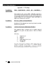
Appendix A - Warnings


WARNING: 

THIS EQUIPMENT MUST BE EARTHED / 

GROUNDED 
 

This equipment relies on the EARTH / GROUND connection to 
ensure safe operation such that the user and TELECOM Network 
are adequately protected. It must not under any circumstances be 
operated without an earth connection, which could nullify its 
approval for connection to a network. 


WARNING: INSTALLATION 

OF 

EQUIPMENT 


Installation of this equipment must only be performed by suitably 
trained service personnel.


WARNING: 

CONNECTION OF OTHER EQUIPMENT 


This equipment allows connection only of suitably approved 
equipment to its ports, the safety status of which are defined 
below. 

 
   SELV 

Ports: 


i)

 Supervisor

 port 


ii)

 MAIN

 port 

    iii)

 D&I

 port 


iv)

 CH1

 to 

CH4

 (Channel ports) 


v)

 EXT 

CLOCK


vi)

 ALARM

 port 


The above named ports are classified as SELV (Safety Extra Low 
Voltage) in accordance with in Clause 2.3 of EN60950 (BS7002, 
IEC950 as applicable), and 

must only

 be connected to equipment 

which similarly complies with the SELV safety classification. 

Содержание Echo MXU9070

Страница 1: ...iplexer Jan 97 Version 1 1 TECHNICAL SALES FAX ADDRESS WEB 0118 965 6000 0118 965 5100 0118 965 5001 464 Basingstoke Road Reading Berkshire RG2 0QN www blackbox co uk Echo Mux X 21 V 11 MXU9070 Echo M...

Страница 2: ...w black box ch Web Site www blackbox com Netherlands Mexico Black Box Datacom BV Black Box De Mexico S A de C V Tel 03032417799 Tel 05 420 0100 Fax 0302414746 Fax 05 420 0123 Web Site www blackbox nl...

Страница 3: ...en fitted in accordance with the installation instructions against the following directives standards Low Voltage Directive 73 23 EEC and amendment 93 68 EEC EN60950 1992 Safety Electromagnetic Compat...

Страница 4: ...anges 12 Local or Remote Configuration 12 Changing the configuration page 12 Nx64 channel Configuration 13 Timeslot Assignment 13 Drop and Insert D I channel operation 15 Setting the System s Real Tim...

Страница 5: ...Diagnostics Loopbacks 29 Appendix A Warnings 30 Appendix B Approval 33 Appendix C EMC Requirements 34 Limitation of Emissions 34 D Type Connections 34 Mains Connection 35 To Ensure that adequate immun...

Страница 6: ...is available in the appendices Functional overview The ECHO E1 multiplexer is a time division multiplexer operating at 2 048 Mbps compliant with both EUROPEAN and UK G 703 standards The composite link...

Страница 7: ...xer TECHNICAL 0118 931 2233 Typical Applications The Echo may be used to provide up to 4 Nx64K X 21 V 11 channel connections at any multiple of 64K between two sites using a G 703 2 Megabit Second dat...

Страница 8: ...to Nx64 X 21 V 11 ports the optional Drop and Insert card is used as follows The Echo is set so that the slots used by the PABX are passed through to the main G 703 link transparently This is describe...

Страница 9: ...reset the Echo Time Division Multiplexer is set to operate with all channels set as follows Rate Off Mode NORMAL TX Clock INT RX Clock INT Indicate ON Changing the Configuration The Echo may be confi...

Страница 10: ...lowing 1 VT52 2 VT100 3 ADDSVP 4 ADM3A 5 H1500 6 N8009 7 TVI920 2 MEGABIT E1 MULTIPLEXER V1 00 15 35 16 09 96 Main Link EUR SYNCHRONISED Mode NORMAL Nx64 Channels 4 Framing CRC4 D I Channels NOT FITTE...

Страница 11: ...ly a few keys are required to configure the Echo multiplexer and are summarised as follows Right arrow Moves the cursor to the next field to the right Left arrow Moves the cursor to the next field to...

Страница 12: ...e local and remote end as necessary and held in Non Volatile Memory NVRAM Abandoning Changes Pressing ESC at any point before a configuration is updated will cause the message Abandon Changes y n to a...

Страница 13: ...on the Supervisor port terminal keyboard eg Pressing 1 Assigns the slot to Nx64 Channel 1 2 Assigns the slot to Nx64 Channel 2 3 Assigns the slot to Nx64 Channel 3 4 Assigns the slot to Nx64 Channel...

Страница 14: ...ock is supplied by device connected to channel port using X A and X B pins for TX data See note below RX Clock INT Clock is supplied by MUX to device connected to channel using S A and S B pins for RX...

Страница 15: ...s well as mode settings are also set on this page For more details of these link settings see the main link parameter settings section page 24 When the D I card is fitted it is also possible to slave...

Страница 16: ...Remote Main Link p Remote D I Link if fitted These pages are accessed by moving the cursor to the Statistics field using the spacebar to select either the main link or the D I link if fitted The loca...

Страница 17: ...eviations are used BVC Bipolar Violation Count errors BER Approximate Bit Error Rate based on BVC which may be used to trigger an alarm Note that BER is only calculated when the unit is in SYNC with t...

Страница 18: ...arm port Two general purpose relay contact pairs are provided for use with the Echo Separate changeover contacts are provided for both MAJOR and Minor Alarms The contacts may be connected to external...

Страница 19: ...ay also indicates the highest active alarm status None Minor or MAJOR to the right of the Alarm page prompt on the top right of the screen The reasons for which an alarm may be reported as FAULT are i...

Страница 20: ...ve not been connected at all Note that un connected CONTROL inputs will produce a random ON or OFF indication Control inputs from ports which are not allocated in the timeslot map are ignored Nx64 Clo...

Страница 21: ...will result in a MINOR alarm being generated locally when any remote alarm is active In this way D I remote alarms may be carried on through the main link so that connected peripheral equipment can c...

Страница 22: ...he Echo Multiplexer must be operated under the following atmospheric conditions Temperature 0 to 40 degrees centigrade Humidity 0 to 90 non condensing Air Pressure 86 to 106 kPa Mechanical Constructio...

Страница 23: ...ted on the main set up screen as either UK or EUR as appropriate Composite Network Connection The Echo Time Division Multiplexer supports both UK 75 Ohm and European Network Interfaces The composite p...

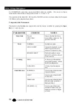
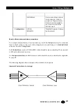
Страница 24: ...CRC4 Hunt Lost Shows whether the link is successfully connected No options selectable Mode NORMAL Normal run mode LOCAL LOOP Composite loopback causes MUX to get carrier even when not connected to lin...

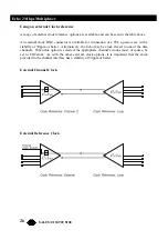
Страница 25: ...simple demonstration or local network use two Echo Multiplexers may be connected back to back using a cross over cable arrangement one unit being set to internal clock reference the other to loop cloc...

Страница 26: ...connection of a TTL square wave with a stability of 50ppm or better Alternatively the Echo may be clock slaved to one of the data channels When this option is selected the appropriate channel s clocks...

Страница 27: ...27 Echo 2 Mbps Multiplexer TECHNICAL 0118 931 2233 Through Clock Master from D I link In this example the master clock is derived from the PABX which is connected to the D I channel...

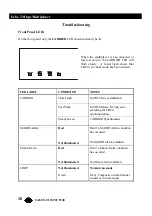
Страница 28: ...entered LED LABEL CONDITION NOTES CARRIER Slow Flash No RX Carrier established Fast Flash In CRC4 Mode FAS present searching for CRC4 synchronisation Steady Green CARRIER Synchronised MAJOR Alarm Red...

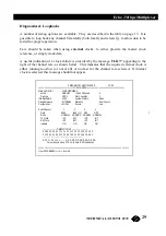
Страница 29: ...oo slow or not at all or too fast for the channel rate selected If internal clock is selected this message should not appear 2 MEGABIT E1 MULTIPLEXER V1 00 15 35 16 09 96 Main Link EUR SYNCHRONISED Mo...

Страница 30: ...EQUIPMENT Installation of this equipment must only be performed by suitably trained service personnel WARNING CONNECTION OF OTHER EQUIPMENT This equipment allows connection only of suitably approved e...

Страница 31: ...nstallation des Ger tes Die Installation des Ger tes darf nur von entsprechend ausgebildetem und autorisiertem Personal durchgef hrt werden Warnung Anschlu von anderen Ger ten Angeschlossen werden d r...

Страница 32: ...convenablement form s ce type de mat riel Mise en garde Connexion d autres quipements Des quipement compl mentaires pourrant tre connect s aux ports de cet quipement la seule condition que ceux ci soi...

Страница 33: ...mbols and approval number is approved for connection to the networks identified in this Appendix as follows G 703 In the UK to PD7024 75 Ohm Un balanced via 2 x BNC connectors The internal link must b...

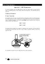
Страница 34: ...for connection to the 15 way D Type ports The cables must have the foil or braid screen connected effectively to the metal headshell to ensure continued compliance The following headshells provide sui...

Страница 35: ...s in the user s interest to ensure continued product immunity against mains born transients and static discharge To achieve this it is important to ensure that equipment is effectively earthed The mai...

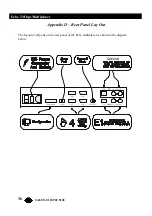
Страница 36: ...36 Echo 2 Mbps Multiplexer SALES 0118 965 5100 Appendix D Rear Panel Lay Out The layout of all ports on the rear panel of the Echo multiplexer is shown in the diagram below...

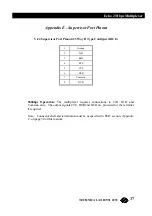
Страница 37: ...gured DCE 1 Ground 2 TxD 3 RxD 4 RTS 5 CTS 6 DSR 7 Common 8 DCD 9600bps Operation The multiplexer requires connections to TxD RxD and Common only The output signals CTS DSR and DCD are provided for th...

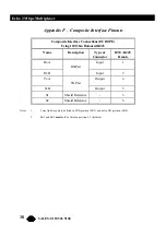
Страница 38: ...120 Ohm Balanced RJ45 Name Description Type at Connector DTE RJ45 Female RxA RX Pair Input 1 RxB Input 2 TxA TX Pair Output 4 TxB Output 5 S1 Shield Reference 3 S2 Shield Reference 6 Notes 1 5 way li...

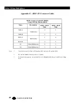
Страница 39: ...B Ground Reference Outer RX2 TxA TX Pair Output Centre TX TxB Ground Reference Outer TX3 Notes 1 5 way link strap must be fitted in UK position LK4 and not in EUR position LK3 2 Fit LK1 position 1 2 t...

Страница 40: ...TE1 RJ45 Male TxRxA TXRX Pair 4 1 TxRxB 5 2 RxTxA RXTX Pair 1 4 RxTxB 2 5 S1 Shield Reference 6 3 S2 Shield Reference 3 6 Notes 1 5 way link strap must be fitted in EUR position LK3 and not in UK posi...

Страница 41: ...CE DB15 Female Protective Ground 1 G Signal Ground 8 T A TxD a Input 2 T B TxD b Input 9 R A RxD a Output 4 R B RxD b Output 11 S A Clock a Output 6 S B Clock b Output 13 I A Indicate a Output 5 I B I...

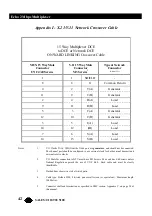
Страница 42: ...6 S A Load 14 13 S B Load Notes 1 V11 Clocks X A X B from the Nx64 port are generators and should not be connected The channel port should be configured to use external clock for both external transm...

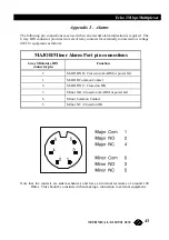
Страница 43: ...SELV equipment as follows MAJOR Minor Alarm Port pin connections 6 way Miniature DIN connector pin Function 2 MAJOR NO Closed on ALARM or power fail 1 MAJOR Common Contact 4 MAJOR NC Closed on OK 3 M...

Страница 44: ...nor Alarm contacts Nx64K DATA CHANNELS Interface X 21 V 11 DCE Capacity Echo Mux Echo T Mux 2 4 Channels Data Rates Off 64K 128K 1984K in 64K steps Internal or External Clocks Data Format Synchronous...

Отзывы: