Rev. 1.00
- 88 -
SRP-275II
6. Adjustments and Maintenance
6-1 Adjustment
When assembling this printer, be sure to refer to the required adjustment procedure. To ensure normal
operation of the printer after disassembly or replacement of a Component for maintenance or repair. Be sure
to perform along to the required method.
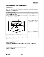
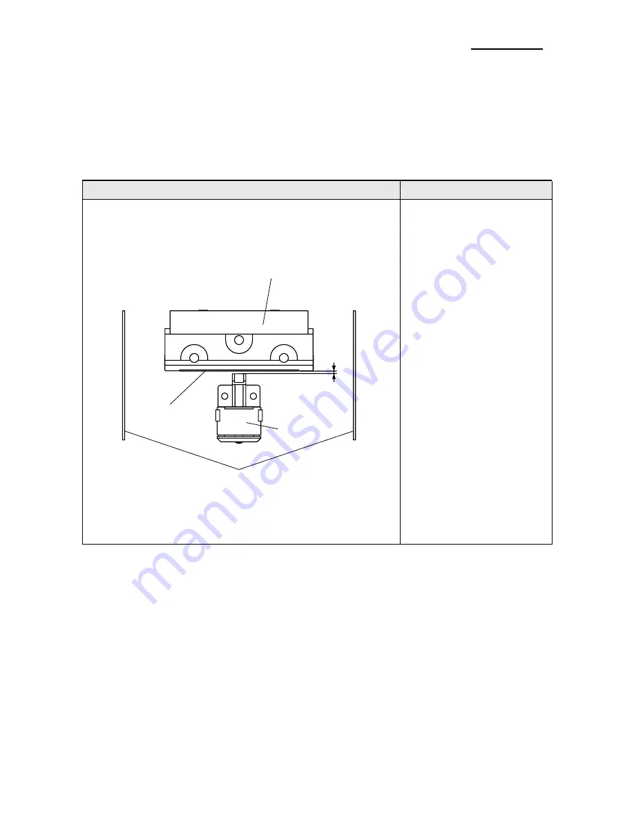
6-1-1 Adjustment of Head gap
Adjustment step and description points
In Adjustment
1) Move the
Printer-head
to L side.
2) Insert the thickness gauge between
Printer-head
and platen, then
rotate the
AD-lever L
and adjust the gap.
Gap
0.
4
0~
0.5
0
Printer-head
Frame-main
Platen
Holder platen
3) Move the
Printer-head
then check if the proper gap from R side
center has been achieved.
4) If head gap is not proper, adjust head gap by rotating
AD-lever R
.
Appropriate gap: 0.40~0.50mm
In order to make the gap narrow
(wide), turn
AD-lever
to mark
‘-(+)’
If gap is not correct, repeat once
more.
6-1-2 Replacement of Printer-head
Follow below steps for replacing
Printer-head
.
1) Loosen the
Frame-ribbon.
2) Disassemble the
Printer-head
from the
Carriage head ass’y
and take out the
FPC-head
from the
connector of PCB ass’y.
3) Replace the
Printer-head
and assemble, according to the order of
Sub-assembly E
.
4) After assembling, adjust the gap as above “Adjustment” indicates.
5) Assemble the
Frame-ribbon
.

