background image

SignalHawk™ PC and Rack Mount Models

59

Carrier-to-Interference Ratio

Calculates the ratio of the carrier signal power to the power level of the noise 
and interference signals. 

To determine the ratio, two measurements need be done. First sweep should 
be the carrier and interferer. The second sweep should be the interferer alone.

Note:


Because the transmitted carrier must be turned off for the 

second portion of this measurement, access to the transmitter is 
needed to complete this procedure.

1.

Do one of the following:

Move marker to the desired frequency.

Note:


The default marker placement assumes the carrier to be 

measured is the center of the frequency span. It can be moved via 
the arrow keys and/or wheel.

Select Marker to Max Peak to quickly identify the signal to be 
measured.

2.

Measure the carrier signal.

3.

Turn off the transmitter.

4.

Measure the noise and interference signal levels as follows: 

Note:


The carrier power and interferer power will be displayed in 

selected power units, and the ratio in dB.

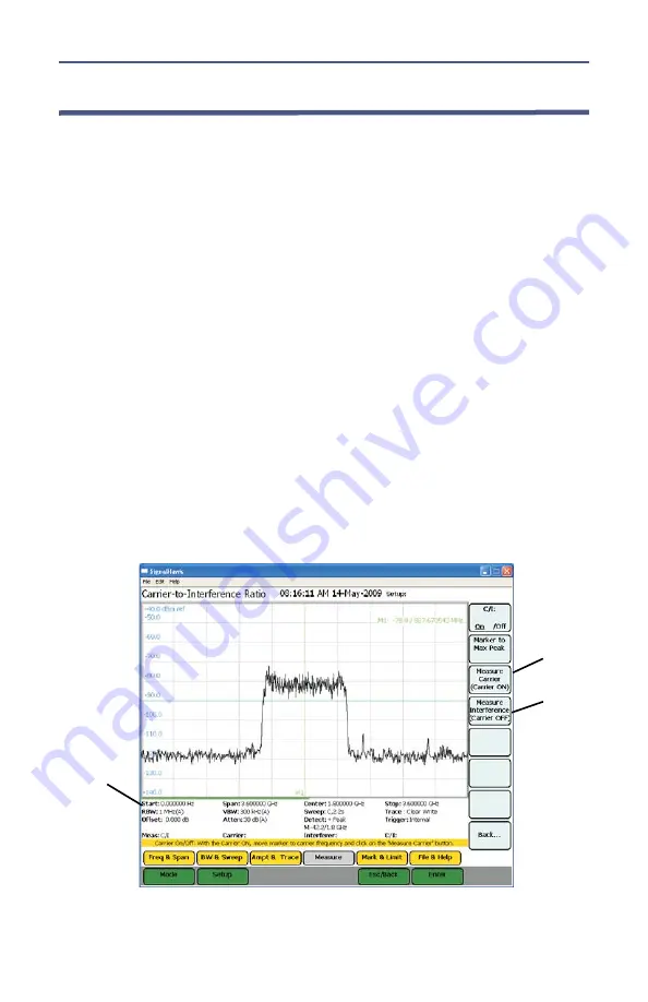
Figure


48  


Example, Carrier-to-Interference Ratio - Carrier On

Measurement 
Settings

STEP 2

STEP 3

Note:


In the status area, the carrier power, interferer power 

will be displayed in selected power units, and the ratio in dB.

Содержание SignalHawk SH-36S-PC

Страница 1: ...016 by Bird Technologies Inc Instruction Book Part Number 920 SHPC OPS Rev F SignalHawk is a trademark of Bird Electronic Corporation ActiveSync Microsoft and Windows are registered trademarks of the Microsoft Corporation Adobe Acrobat Reader are registered trademarks of Adobe Systems Incorporated ...

Страница 2: ...t to remove the RF transmission line while RF power is present WARNING Do Not Service Or Adjust Alone Under no circumstances should any person reach into an enclosure for the purpose of service or adjustment of equipment except in the presence of someone who is capable of rendering aid WARNING Safety Earth Ground An interruptible earth safety ground must be supplied from the main power source to t...

Страница 3: ...re for emphasis WARNING When using the AC adapter connect the AC plug only to a properly grounded receptacle Serious injury or death can occur if not properly grounded See page 5 WARNING Care should be taken when handling batteries Keep out of the reach of children Do not heat or dispose of batteries in fire May burst or release toxic materials Avoid forced discharge Do not short circuit Restrict ...

Страница 4: ...ill damage the SignalHawk If unsure of power levels measure the test connection with a power sensor before using the SignalHawk See pages 7 and 21 CAUTION Avoid installing the SignalHawk near equipment that exhausts or radiates excessive heat such as power amplifiers or DC power supplies Proper ventilation should always be considered as part of the installation location See page 12 CAUTION Harsh o...

Страница 5: ...EGURIDAD DEL INSTRUMENTO BENUTZUNG WIRD DAS GERÄT AUF ANDERE WEISE VERWENDET ALS VOM HERSTELLER BESCHRIEBEN KANN DIE GERÄTESICHERHEIT BEEINTRÄCHTIGT WERDEN UTILISATION TOUTE UTILISATION DE CET INSTRUMENT QUI N EST PAS EXPLICITEMENT PRÉVUE PAR LE FABRICANT PEUT ENDOMMAGER LE DISPOSITIF DE PROTECTION DE L INSTRUMENT IMPIEGO QUALORA QUESTO STRUMENTO VENISSE UTILIZZATO IN MODO DIVERSO DA COME SPECIFIC...

Страница 6: ...UNG DES GERÄTES GELTEN NUR FÜR GESCHULTES FACHPERSONAL ZUR VERMEIDUNG GEFÄHRLICHE ELEKTRISCHE SCHOCKS SIND WARTUNGSARBEITEN AUSSCHLIEßLICH VON QUALIFIZIERTEM SERVICEPERSONAL DURCHZUFÜHREN ENTRENTIEN L EMPLOI DES INSTRUCTIONS D ENTRETIEN DOIT ÊTRE RÉSERVÉ AU PERSONNEL FORMÉ AUX OPÉRATIONS D ENTRETIEN POUR PRÉVENIR UN CHOC ÉLECTRIQUE DANGEREUX NE PAS EFFECTUER D ENTRETIEN SI L ON N A PAS ÉTÉ QUALIFI...

Страница 7: ...UTORIZADO PUEDE REEMPLAZARLAS GERÄTE SIND MIT WIEDER AUFLADBAREN BATTERIEN BESTÜCKT BATTERIEN SIND NUR VON QUALIFIZIERTEM SERICE PERSONAL AUSZUWECHSELN CES DISPOSITIFS SONT ÉQUIPÉS DE BATTERIES RECHARGEABLES SEUL LE PERSONNEL D ENTRETIEN AUTORISÉ EST HABILITÉ À LES REMPLACER LE UNITÀ SONO DOTATE DI BATTERIE RICARICABILI CHE DEVONO DA COME SPECIFICATO DAL PRODUTTORE LA PROTEZIONE DI SICUREZZA POTRE...

Страница 8: ... UNE TENSION ET UN FUSIBLE CORRECTS CONSULTER LE MODE D EMPLOI USE LA INSTALACION Y FUSIBLE DE VOLTAJE CORRECTO VEA EL MANUAL AUSSCHLIESSLICH VORSCHRIFTSMÄSSIGE WECHSELSPANNUNGS EINSTELLUNG UND SICHERUNG BENUTZEN SIEHE DAZU HANDBUCH UTILLIZZARE TENSIONE E FUSIBLE ADATTI FARE RIFERIMENTO AL MANUALE ...

Страница 9: ...roduction Describes the features of the Bird SignalHawk lists equipment supplied and optional equipment and provides power up instructions Settings Describes how to connect SignalHawk to the user s system describes the spectrum analyzer measurements and provides quick start steps for each measurement Measurements Describes the power measurement feature lists compatible power sensors describes how ...

Страница 10: ...er Connector 6 DC Supply 6 Spectrum Analyzer Quick Start 7 Chapter 2 PC SignalHawk Set Up 9 Installing the SignalHawk Program 9 Chapter 3 Rack Mount SignalHawk Set Up 12 Installing the SignalHawk into a Rack 12 Connecting the Rack Mount via USB Connection 13 Connecting Remotely via LAN WAN Connection 15 Configuring a Basic Network Connection 15 Connecting a Remote Computer to the Host Computer 19 ...

Страница 11: ...p 26 View Previous Setup 26 Looking At The Screen 27 Freq Span Menu 28 Start Stop Freq and Center Span 29 Wheel Step 29 Full Span 29 Freq List 30 BW Sweep Menu 31 Resolution Video BW Modes 32 Resolution Video BW 33 Span RBW 33 RBW VBW 33 Detection Mode 34 Peak Detection 34 Peak Detection 34 Sample Detection 34 Average Power 34 Sweep 35 Single 36 External Trigger 36 External Low Level High Level Ri...

Страница 12: ... Valley 41 Markers Detect 42 Threshold 42 Marker to Max Peak or Marker to Min Valley 42 Marker to Next Peak Left or Marker to Next Valley Left 42 Marker to Next Peak Right or Marker to Next Valley Right 42 All Markers to Max Peaks or All Markers to Min Valleys 42 All Markers Off 42 Marker Delta 42 Marker Display 42 Marker Type 42 All Markers Type to Icon 42 All Markers Type to Line 42 Marker Displ...

Страница 13: ... 46 Full Screen 46 Utility 46 Help 46 Chapter 5 Measurements 47 Spectrum Analysis Measurement 48 Occupied Bandwidth Measurement 49 Threshold Modes 49 49 dBc 49 Setting Occupied Bandwidth 49 Channel Power Measurement 51 Setting Channel Power 51 Adjacent Channel Power Measurement 53 Time Domain Zero Span 55 Field Strength Measurement 56 Received Signal Strength Indicator RSSI 57 Demodulate Signal 58...

Страница 14: ...nloading and Installing Software 68 Installing the PC Tool Software 68 Menu Bar 69 File 69 Edit 69 View 69 Tools 69 Measurements 69 Communicate 69 Tool Bar 70 Save 70 Open 70 Cut 70 Copy 70 Paste 70 Delete Trace 70 Return to Normal Mode 71 Zoom In 71 Zoom Out 71 Autoscale Graph 71 Add Markers 71 Add to Upper Limit Line 71 Add to Lower Limit Line 71 Delete Markers or Limit Lines 71 Option Dialog Bo...

Страница 15: ... 79 Updating the Firmware on a Remote Rack Mount SignalHawk 80 Troubleshooting 82 Customer Service 83 Specifications 84 SH 36S RM 84 Distortion DANL 89 SH 36S PC 89 Parts List 94 Optional Accessories 95 SH 36S PC 95 General 95 Test Cables and Adapters 96 SH 36S RM 97 General 97 Test Cables and Adapters 97 ROHS 98 Appendix 1 Menu Maps 99 Spectrum Analyzer Menu Maps 99 Setup Function Menu Maps 106 A...

Страница 16: ...f Radio Frequency RF and wireless systems The model number is identified on the unit and also on the display screen at the end of the power on sequence The firmware installed on the SignalHawk is updated on a regular basis The operator s manual covers the most recent upgrade to the firmware up to the date listed on the manual See Troubleshooting on page 82 ...

Страница 17: ...SignalHawk Rack Mount Hardware and Software Supplied 2 5 6 1 7 3 4 Item Description 1 Car Adapter Cable 2 USB Cable 3 Software CD 4 AC Power Adapter and Cord 5 PC SignalHawk 1 Rack Mount SignalHawk 2 USB Cable 3 Fuse Drawer with Shorting Bar 4 2 SLO BLO 5mm x 20mm 63A Fuses 5 AC Power Cord 6 Ethernet Cable 7 Software CD ...

Страница 18: ... Indicators 1 2 3 4 5 6 7 8 Item Description 1 Spectrum Analyzer Port N F RF input 20 dBm max 2 BNC F external trigger input 5V TTL 3 2 1mm DC jack for external power supplies 4 Battery Charge Indicator 5 USB Type B for PC connection 6 Charge Indicator Light 7 Power Switch 8 USB Host Power Indicator ...

Страница 19: ...r 5 Fan 6 PS 2 Keyboard Mouse Connectors 7 RS 232 Connector 8 Parallel Port 9 VGA Port 10 USB Connectors 11 LAN Connector 12 AC Power Connector 13 AC Power Switch 14 Ground Post 15 External 12 24 48 VDC Connector 16 BNC F external trigger input 5V TTL 17 Spectrum Analyzer Port N F RF input 20 dBm max 18 Pass Thru LAN Connector 19 USB Type B for PC connector CAUTION Do not block the fan s airflow t...

Страница 20: ...internal battery Note The charge LED will be steady amber while charging and steady green when fully charged Charge Indicator Light The charge indicator light on the PC SignalHawk has a dual function Power Source Light Color Condition External Power Amber Charging battery Green Battery fully charged Battery Power None light is off 100 to 30 Power Available Yellow Below 30 Power Available When the ...

Страница 21: ...2 pole fuse tray fuse on both lines the other is a single fuse tray line fuse shorting bar on neutral Check with local regulations to determine whether single or dual pole fuse protection is required 3 Install one or both fuses into the appropriate fuse drawer 110VAC operation 5x20mm SLO BLO 1 25A 220VAC operation 5x20mm SLO BLO 0 63A 4 Replace fuse drawer into the power entry module 5 Insert AC p...

Страница 22: ...ns connect directly to the output of the signal source See the below graph For high power connections use a directional coupler or attenuator to reduce the output level of the signal source See the below graph 3 Power up the SignalHawk 4 In the Start Menu use the arrow keys to highlight the desired measurement and press Enter 5 In the Freq Span Menu set the frequency range See Freq Span Menu on pa...

Страница 23: ...erference Ratio on page 59 Out of Band and In Band Out of Channel Spurious on page 61 Water Fall Spectrogram on page 40 8 Turn on markers or limit lines if needed see Marker On Off on page 41 and Limit Lines on page 43 9 Make a sweep 10 In the File Help Menu click on Quick Save Trace to save the data see File Help Menu on page 45 ...

Страница 24: ...support center for any security updates Typically if Automatic Updates are configured on the host PC these will be automatically flagged and selected for download and installation Note The installation utility will launch after the OS prerequisites are installed 5 Do one of the following Accept the default installation location Select a different folder 6 Select Next and the installer will complet...

Страница 25: ...sh in the Completing the Found New Hardware Wizard window Figure 6 Completing the Found New Hardware Wizard 14 Launch the SignalHawk program Note PC SignalHawk can be used in any orientation 15 Select the unit from the DSP Device List if necessary 16 Connect RF signal 17 Connect a TTL trigger source to the BNC connector if necessary ...

Страница 26: ...SignalHawk PC and Rack Mount Models 11 Figure 7 Select DSP Device List ...

Страница 27: ...proper power supply See Power Supply Rack Mount SignalHawk on page 6 3 Connect the SignalHawk to a host PC though one of the following Rear USB Rear LAN Note See Rack Mount SignalHawk Connection Diagram on page 18 There are three RJ45 Ethernet jacks on the unit Use the rear LAN connection jack for remote access Note Host control priority is given in the order shown above Example If the normal remo...

Страница 28: ...Prerequisites Installation process 4 Review the End User License Agreement check I accept the terms of the License Agreement and select Install Note The install utility will install the prerequisites This may take several minutes Note When completed check with Microsoft support center for any security updates Typically if Automatic Updates are configured on the host PC these will be automatically ...

Страница 29: ... software automatically in the Found New Hardware Wizard window Note This procedure is performed when connecting either a PC or Rack Mount SignalHawk for the first time Driver installation is required for every distinct SH 36S PC or SH 36S RM connected to the computer Figure 9 Found New Hardware Wizard 11 Click Next 12 Follow the instructions that are presented 13 Click Finish in the Completing th...

Страница 30: ...es to the client computer it is highly recommended to create a System Restore Point a Click Start b Go to Programs or All Programs c Go to Accessories d Go to System Tools e Select System Restore Note Permissions affiliated with being an administrator or a member of the Administrators group are needed in order to complete this procedure If the computer is connected to a network network policy sett...

Страница 31: ...e the following IP address 192 168 1 11 e Specify a subnet mask In Subnet Mask type the following 255 255 255 0 Note Default IP settings for the Rack Mount are IP address 192 168 1 10 and Subnet Mask 255 255 255 0 DHCP is NOT enabled by default on the Rack Mount Note Use automated IP settings DHCP whenever possible for the majority of client computers DHCP is enabled by default and when automated ...

Страница 32: ...tion or by logging in locally to the Rack Mount using an external monitor keyboard and mouse not included connected to the I O ports on the back panel of the unit Consult the network administrator for proper configuration Note Other programs may be used on the Rack Mount Hawk as long as they directly support its specific use or provide system utilities resource management anti virus or similar pro...

Страница 33: ... 11 Rack Mount SignalHawk Connection Diagram RF MODULE Mini ITX PC USB USB ETHERNET ETHERNET Rack Mount Signal Hawk Local PC Laptop Remote PC RF IN ETHERNET HUB ROUTER Pass thru connection allows convenient access to hub through front panel ...

Страница 34: ...he Rack Mount is SH 36S RM and the default IP address and Subnet mask is 192 168 1 10 and 255 255 255 0 4 Click Connect 5 When the Log On to Windows dialog box appears type your user name password and domain if required and then click OK 6 The Remote Desktop window opens and you see the desktop settings files and programs that are on your host computer which in this example is the Rack Mount Your ...

Страница 35: ...ing the Password on Auto Logon 1 Go to the Start Menu 2 Select All Programs 3 Select Bird Technologies Group 4 Go to Utilities 5 Go to Automatic Logon Utility 6 Enter a username and new password 7 Click Ok Figure 12 Automatic Logon Utility ...

Страница 36: ... menu list use the mouse scroll wheel or the up and down arrow keys to move the highlight bar through the list Use the left and right arrow keys to move to a different list box Spec Analysis Menu Key Click here to enter the Spectrum Analyzer mode Utilities Menu Key Click here to display the Utility Menu main screen The Utilities menu provides information about the instrument software amount of ava...

Страница 37: ...rement being used 2 Menu Selection labels 3 Go to the Help menu Select Esc Back to return here There are two functions in the help menu 4 Enter goes to a menu Esc will exit a menu 5 Go to the Utilities menu See Utilities on page 62 6 Go to setup screen 7 Go to mode selection screen 8 Menu key labels 9 Selected measurement highlighted 10 Name and brief description of highlighted measurement 11 Curr...

Страница 38: ...up Menu Quick Save Setup The saved settings are stored as a file in the internal drive of the host PC Each quick save is stored in a separate file that is named using the date time file naming format GeneralSA MM DD hh mm ss shs where YYYY is the year the first MM is the month DD is the day HH is the hour the second MM is the minute and SS is the second of the time when the file was saved ...

Страница 39: ...tup 1 Click on Save Trace 2 Enter a file name Recall Setup Recalls a saved setup and sets the instrument parameters to run the recalled setup Recall Default Setup Recalls the factory default setup and sets the instrument parameters to run this setup Manage Setup Files Allows access to the file management of the saved Setups ...

Страница 40: ...tup Files Delete Deletes the selected Setup on the list Delete All Setups Deletes all of the Setups on the list View Setup See View Setup on page 25 in the Setup Menu View Setup Displays the properties of a selected saved Setup on the list Figure 17 Setup View Setup ...

Страница 41: ...e Deletes the displayed Setup Top of List Displays the Setup from the top of list of saved Setups Bottom of List Displays the Setup from the bottom of list of saved Setups View Next Setup Displays the next Setup on the list of saved Setups View Previous Setup Displays the previous Setup on the list of saved Setups ...

Страница 42: ... 6 7 5 3 2 8 10 11 9 Item Description 1 Name of selected measurement 2 Sweep display area 3 Marker 4 Date and time 5 Name of setup file being used 6 Menu selection labels 7 Menu key labels 8 Help tips for the current screen 9 Measurement settings 10 Sweep progress bar 11 Data trace 12 System key labels ...

Страница 43: ...ds Set the Center Freq and Freq Span Set the Start Freq and Stop Freq Select the Full Span of the instrument Select a band from the Freq List The most common of these methods is to set the center frequency and a frequency span a range and let SignalHawk calculate the start and stop frequencies for the sweep Reducing the span by default with RBW and VBW both on auto mode will usually speed up the s...

Страница 44: ...When done press enter to keep the same frequency units or click the menu selection corresponding to the desired units Wheel Step When another frequency function is active and the mouse scroll wheel is turned the value will change in steps of the Wheel Step After clicking Wheel Step to highlight it the following is enabled Up Down Arrow Keys and Mouse Scroll Wheel Change the step value by a small a...

Страница 45: ...ds Use the up down arrows or mouse scroll wheel to scroll to the desired band then press Enter to use it Recently used bands are displayed at the top of the list Note Channelized bands are denoted on the Frequency List by a plus sign Figure 20 Example Freq List Recently Used Bands ...

Страница 46: ...n the screen This is the minimum resolvable frequency spacing The menu selections legend displays the current value Figure 21 Signal Representation Actual Input RBW Separation RBW Separation Separation 3 dB Lowering the RBW will lower the noise floor which can make low power signals easier to see and makes readings close to the noise floor more accurate Figure 22 Example BW Sweep Menu Click on the...

Страница 47: ...an and the values of Span RBW and RBW VBW If either the RBW or VBW is changed these will switch to manual Auto RBW sets the RBW based upon the frequency span When in Auto mode the RBW is set according to the nearest ratio of the Span RBW selection The default ratio is 300 When the frequency span is reduced the RBW will also be reduced accordingly Example When the span is changed to 3600 MHz the RB...

Страница 48: ...ith frequency span when the Resolution BW mode is in Auto This value is ignored when Resolution BW Mode is in Manual mode The menu selection legend displays the current value Up and Down Arrow Keys Press these keys to increase or decrease the ratio in steps of one Left and Right Arrow Keys Press these keys to enter the minimum ratio left arrow or the maximum ratio right arrow Mouse Scroll Wheel Ro...

Страница 49: ...or narrow bandwidth signals In zero span mode this mode acts like a peak detector and can be used to show AM band frequencies Peak Detection Returns the minimum value of the data collected for each display pixel Recommended for displaying the difference between CW and pulsed signals Sample Detection Returns a sample of the data collected for each display pixel Use this method for noise like signal...

Страница 50: ...ep Sweep sets up the properties of individual sweeps that the SignalHawk performs It can set whether the sweeping is continuous or single and the properties of video triggers if enabled Figure 25 Example Sweep More Figure 26 Example Trigger Rep ...

Страница 51: ... See External Trigger below External Single See External Trigger below Note Useful for signals that are time varying Ones that change slow enough to trigger manually as well as carrier interference ratios See Carrier to Interference Ratio on page 59 Arm Trigger Manually initiates a sweep External Trigger External Low Level High Level Rise Edge Fall Edge Either Edge Low Level Triggers if input 0 0 ...

Страница 52: ... condition occurs again and it performs another sweep This is used in zero span mode In order to use this function the trigger condition needs to be set up 1 Monitor the RF data to determine the trigger condition 2 Set the power level at center freq 3 Set the trigger level High Level Trigger if dBm rises ABOVE the power level Low Level Trigger if dBm falls BELOW the power level Pwr Level Set the p...

Страница 53: ... This soft key is not displayed if the Units of measure is in Volt or Watt See Units on page 39 Attenuation Controls the built in attenuator on the signal input This reduces the amplitude of a high powered signal The attenuation can be set to Auto or at levels of 0 10 20 and 30 dB The reported value of the signal is automatically corrected for the selected attenuation Note When the Reference See R...

Страница 54: ...or a true signal level reading 1 Measure the total amount of loss for all attached signal devices 2 Enter the measured amount as the Offset value or gain Example The system has 10 dB of loss due the use of a coupler enter the value of 10 in the Offset Offset range is 100 to 100 Units dBm dBm 10 Log Power Watts 30dB dBuV dBm dBuV 10 50 log 90 dBmV dBm dBmV 10 50 log 30 dBV dBm dBV 10 50 log 30 Volt...

Страница 55: ...f multiple readings Water Fall Spectrogram The Water Fall Spectrogram shows how the spectral density of a signal varies with time and presents it in a visual image Also known as spectral waterfalls sonograms voiceprints or voicegrams spectrograms are used to identify phonetic sounds and specific noise disturbances 1 Go to the Ampt Trace menu 2 Click on the Trace selection 3 Click on the Water Fall...

Страница 56: ...rkers to choose from measurements that use some of the markers for data display have less selectable markers Pressing the soft key will cycle through each of the six markers Marker On Off Turns a Marker on and off Marker to Max Peak Moves the active marker to the highest point on the trace Markers to Peak Valley Figure 31 Markers to Peak Valley ...

Страница 57: ... 42 progressing to the left Marker to Next Peak Right or Marker to Next Valley Right Cycles the active marker to the right through the points on the trace either from highest peaks or lowest valleys See Markers Detect on page 42 progressing to the right All Markers to Max Peaks or All Markers to Min Valleys Sets all the markers to either the maximum peaks or minimum valleys depending on the functi...

Страница 58: ...bles the frequency read out of all displayed markers to read the exact frequency of the peak within the pixel to a resolution of 1 Hz Note Signals that vary in frequency must be within the RBW to obtain accurate results Limit Lines Limit lines give notification of when a signal has reached or gone over a set measurement amount Limit lines can be moved with arrow keys Note All valid traces are blac...

Страница 59: ...ask is selected it is controlled by the following options Freq Lock Locks the mask onto the selected band even if the frequency is changed EM to Max Peak Sets mask s reference level to the maximum peak in each sweep Figure 33 Example Limit Line Mask ...

Страница 60: ...ves the trace that is displayed on the screen 1 Click on File Help 2 Click on Quick Save Trace Note The trace is stored as a file in the default file location of the host PC Each quick save is stored in a separate file that is named using the measurement and date time file naming format Measurement name MM DD HH MM SS shf Where the first MM is the month DD is the day HH is the hour the second MM i...

Страница 61: ...e is orange The current trace is black Clear Recalled Trace Deletes the highlighted trace Manage Trace Files Copy trace files to and from network drives and delete traces Delete Trace Deletes a selected trace Delete All Traces Deletes all traces in the directory Full Screen Enlarges the graph area to the size of the whole screen Press escape to go back to regular screen Utility See Utility Main Me...

Страница 62: ...zer mode the following measurements can be used Spectrum Analysis Measurement on page 48 Occupied Bandwidth Measurement on page 49 Channel Power Measurement on page 51 Adjacent Channel Power Measurement on page 53 Time Domain Zero Span on page 55 Field Strength Measurement on page 56 Carrier to Interference Ratio on page 59 Out of Band and In Band Out of Channel Spurious on page 61 Water Fall Spec...

Страница 63: ...pectrum Analysis measures the power at each frequency in the range shown on the screen From the Spectrum Analyzer list on the Start Menu select Spectrum Analysis then press the Enter key Figure 36 Example Spectrum Analysis Frequency and Span Screen ...

Страница 64: ...ied dB below the carrier level This method is best for measuring dBm power units Setting Occupied Bandwidth Note For the best accuracy set the center frequency so the main or carrier signal is centered on the screen before taking measurements 1 Select either or dBc under Threshold Mode 2 Do one of the following If the Threshold has been selected go the soft key and set the desired threshold via ei...

Страница 65: ...gure 38 Example Occupied Bandwidth STEP 1 STEP 2 Note Limit can be set without changing the Threshold Mode Figure 39 Example Occupied Bandwidth dBc STEP 1 STEP 2 Note Limit can be set without changing the Threshold Mode ...

Страница 66: ...frequency so the signal is roughly centered before taking measurements In addition the span should be 1 5 times as large as the desired channel width 1 Select the Integration Bandwidth IBW Note The IBW is automatically set when a channelized frequency band is selected from the Frequency list 2 Enter the desired bandwidth 3 Select the desired unit Note The default unit is MHz Note The integration b...

Страница 67: ...Measurements 52 Figure 41 Example Channel Power Integration Bandwidth STEP 2 STEP 3 ...

Страница 68: ...hown on the screen Note If a channelized band is selected from the Frequency list these parameters are automatically set 1 Set the width of the central channel Note The central channel can be set to a different frequency width than the adjacent channels but both adjacent channels have the same width 2 Set both adjacent channels 3 Set the Center to Center channel spacing Note Channel spacing is the...

Страница 69: ... Figure 42 Example Adjacent Channel Power STEP 1 STEP 2 STEP 3 Measurement Settings Width Adjacent Channel Adjacent Channel Guardband Guardband Figure 43 Example Adjacent Channel Power Bandwidth Settings STEP 4 STEP 5 ...

Страница 70: ... Select Time Domain in the Measurement Menu Set the Frequency Span to 0 Hz See Freq Span Menu on page 28 2 Press the Sweep Time soft key and enter how long a single sweep should be using one of these methods Note Time range can be set from 1 ms to 100 s Up Down Arrows Step increments of one second Right Left Arrows Step increments of one millisecond Mouse Scroll Wheel Step increments of one second...

Страница 71: ... stop frequencies to the measurement range of the chosen antenna 2 Select Antenna and select the antenna type from the drop down list Note The antenna type valid frequency range and gain in dB relative to an isotropic radiator are shown in the measurement settings area 3 Measure the strength of the signal emanating from a transmission antenna within the frequency range of the antenna connected to ...

Страница 72: ...ngth goes up and slows as it goes down Similar to Water Fall power is linearly mapped to a range of 0 210 using the same range as for the Water Fall for simplicity The beep rate and volume are proportional to the mapped power value at the current marker index Values of zero are equivalent to continuous beeps and 210 are equivalent to a beep every 4 seconds Figure 46 Example Field Signal Strength R...

Страница 73: ...ct the Demodulate Type b Select the type of demodulation desired 2 Set the demodulation carrier frequency a Select the Demod Freq button b Enter the carrier frequency using the number keys c Select the frequency units 3 Set the time to demodulate the signal a Select the Demodulate Time button b Enter a value c Select the time units d Allow audio to play for the demodulate time e Repeat as necessar...

Страница 74: ...lowing Move marker to the desired frequency Note The default marker placement assumes the carrier to be measured is the center of the frequency span It can be moved via the arrow keys and or wheel Select Marker to Max Peak to quickly identify the signal to be measured 2 Measure the carrier signal 3 Turn off the transmitter 4 Measure the noise and interference signal levels as follows Note The carr...

Страница 75: ...Measurements 60 Figure 49 Example Carrier to Interference Ratio Carrier Off STEP 4 Measurement Settings ...

Страница 76: ...outside a system band 1 Click on Mark Limit 2 Click on the Marker 1 2 3 4 5 6 selection to select marker 1 Note The bracketed number indicates the active marker 3 Click on On Off 4 Use the arrow keys the number keys or mouse scroll wheel to move the marker over one of the spurs 5 Compare the value of the marker to the specified allowable level of Out of Band In Band Out of Channel spurious emissio...

Страница 77: ...n then click on Utility To exit the Utility mode press the Esc Back function key to return to the previous screen or press the Mode key to go to the Start Menu screen Utility Click on Utility to go to the Utility Menu When the utility menu is accessed new menu keys and selections for getting help and exiting to the Windows operating system are activated The Utility Menu screen displays status info...

Страница 78: ...ss the up and down arrow keys or use the mouse scroll wheel to scroll through the displayed text Click on Exit Menu or Esc to return to the Utility Menu Custom Help Displays user created help files that have been uploaded to the SignalHawk Exit to Windows Click on this to exit the SignalHawk program Customizing SignalHawk Content 1 Go to the Utilities menu 2 Press the Exit to Windows soft key Note...

Страница 79: ...to the desktop of the PC 6 Open the csv file 7 Add custom information into the list 8 Copy the csv file back into the My Lists directory Note The computer will ask for verification to overwrite the file in the directory 9 Close the My Lists directory window 10 Launch the PC SignalHawk program ...

Страница 80: ...ing minimum requirements Windows 98 or later operating system Internet Explorer version 6 or later Hard disk with 30 MB of free space Installing Windows 7 Drivers for the BTG Signal Hawk 1 Download the appropriate version of Microsoft WMDC Windows Mobile Device Center from here http support microsoft com kb 931937 Note You will have to go through Microsoft Genuine Advantage validation either via A...

Страница 81: ...s Folder 6 Select the new Serial Device Note It will have a yellow caution triangle with an in it which indicates that no driver has been installed 7 Select the Hardware tab and click on Properties for the Serial Device Figure 53 Hardware Tab ...

Страница 82: ... Next button 12 In the left box scroll down and highlight Microsoft 13 In the right box select Microsoft USB Sync Figure 55 Mobile List 14 Click the Next button 15 Click the Yes button in the Update Driver Warning message box that appears 16 Wait while the driver is installed 17 A confirmation box appears indicating success Click the Close button Accept the BitsyX license terms after reading them ...

Страница 83: ...ft ActiveSync and USB Drivers download them from the Bird Technologies SignalHawk website For PC and Rack Mount http birdrf com Installing the PC Tool Software 1 Download and install Microsoft ActiveSync 2 Click on Install PC Interface Tool 3 Save the compressed file to the PC s desktop 4 Double click the compressed file on the PC desktop 5 Click and drag the SHPCTool icon Setup file out of the co...

Страница 84: ...r Limit Lines Autoscale the Trace Set to Normal Mode and Set Options Normal mode is identified by the standard Windows selection cursor arrow pointing to the upper left DTF Settings Cable Vp Loss Start Stop Distance etc can also be viewed Tools Presents access to the units converter Figure 57 Units Converter Measurements Note This option will only appear for VNA traces Presents the various measure...

Страница 85: ...ut Cuts a trace from a graph Copy Copies a trace from a graph Paste Pastes a trace onto a graph Note A trace from one measurement type cannot be placed onto a graph from another measurement type Occupied Bandwidth Channel Power etc The graphs do not match Delete Trace Deletes a trace from a graph Note The last trace on a graph cannot be deleted ...

Страница 86: ... point via a line Third click connects to the second and so on Add to Lower Limit Line Adds a limit line to the graph First click will create a point on the graph with a line Second click will create another point that connects to the first point via a line Third click connects to the second and so on Delete Markers or Limit Lines Deletes a marker a limit line or a point on a limit line When delet...

Страница 87: ... Sets the current trace to a Match measurement display Distance to Fault Sets the current trace to a Distance to Fault display Cable Sets the current trace to a Cable Loss display Smith Sets the current trace to display a Smith Chart Options Dialog Box Opens the pop up Option Dialog box See Options Dialog Box View Options on page 73 DTF Wizard Opens the Distance to Fault Wizard Figure 58 DTF Wizar...

Страница 88: ... 1 Enter the x and y axis 2 Enter the y axis offset 3 Do one of the following Select the Autoscale box Manually enter values for the scales Note The Offset setting for a specific trace is displayed The setting changes when the Trace changes Figure 59 Example Scale Tab Auto scale Units Tab 1 Select the units of measure for the y axis 2 Set the size of text for the entire graph 3 Set whether or not ...

Страница 89: ...he Options window the marker can be moved by clicking on the marker and dragging it to a desired location Figure 61 Example Markers Tab Limits 1 Tab Defines and turns on or off upper lower limit lines Note The options displayed on this tab will change slightly depending on the type of graph opened Note The upper limit fails any datapoints that are above the line Note The lower limit fails any data...

Страница 90: ...limit fails any datapoints that are below the line Note Up to thirty points for both upper and lower limit lines can be set up Using multiple points a bracketed area may be created 1 Click on a segment 2 Drag each segment at its set point to move it up or down Note If a limit line point is disabled it is removed from the list in the Options dialog box Figure 63 Example Limits 2 Tab Figure 64 Multi...

Страница 91: ...d above the graph and on the left Note If a specific trace name is not created the PC tool will create one automatically Other options are to display or hide the title subtitle trace name and trace date on the graph Figure 65 Example Labels Tab GPS If a GPS sensor is attached to the SignalHawk it will display a location and GPS time reading at the bottom of the trace Note This section does not app...

Страница 92: ...rvice Cleaning CAUTION Harsh or abrasive detergents and some solvents can damage the unit and labels Clean the Bird SignalHawk only with a soft cloth dampened with mild detergent and water Do not use any other type of cleaning solution Charging the Battery The internal battery pack will automatically recharge when the SignalHawk is powered from the AC or cigarette lighter adapter Recharging time f...

Страница 93: ...ded value Do not solder the battery directly Do not disassemble apply excessive pressure or deform Avoid placing the battery in reverse polarity Battery disposal method should be in accordance with local and state regulations 1 Remove the four screws securing the back cover to the SignalHawk 2 Remove the back cover 3 Remove the battery pack 4 Detach the power cord from the battery connector 5 Reve...

Страница 94: ...te Wizard Note The wizard will launch and provide step by step instructions 3 Select the DSP and FPGA images to be updated Figure 68 DSP and FPGA Image Selection 4 Connect the unit to the PC via USB cable 5 Turn on the SignalHawk 6 Select Install the software automatically if the Found New Hardware Wizard is presented Note Both program wizards will run co currently See Installing the SignalHawk Pr...

Страница 95: ...ack Mount SignalHawk 1 Go to http birdrf com 2 Download the Rack Mount SignalHawk software upgrade to a local PC 3 Connect the remote computer to the host computer See Connecting a Remote Computer to the Host Computer on page 19 4 Click on Options Local Resources at the start of the Remote Desktop Connection window Figure 71 Remote Desktop Connection Window 5 Select Disk drives Note This will enab...

Страница 96: ... the Connect 7 Click OK to access the local drives from the remote computer 8 Log into the remote computer 9 Stop the Rack Hawk application 10 Copy the PC Hawk software upgrade from the local PC to the Rack Hawk at XXXXXXXXXXXX 11 Double click Setup and follow the upgrade instructions ...

Страница 97: ...unit for service Keys do not respond Unit is Locked Up Turn the unit off and then back on Unit turns off Internal error Turn the unit back on and continue Unit was shut down because the battery was too low to operate the unit Operate the unit from the AC adapter Unit operates erratically System has become unstable Turn off power wait 15 seconds then reapply power Unit ceases to operate locks up Sy...

Страница 98: ...s to be returned for any reason request an Return Material Authorization RMA through the Bird Technologies website All instruments returned must be shipped prepaid and to the attention of the RMA number Bird Service Center 30303 Aurora Road Cleveland Solon Ohio 44139 2794 Fax 440 248 5426 E mail bsc birdrf com For the location of the Sales Office nearest you visit our Web site at http www birdrf c...

Страница 99: ...5 ms per data point to 2000 s full span 1 ms to 100 s zero span Displayed Data Points 705 Resolution Bandwidth RBW 100 Hz to 1 MHz in 1 3 10 steps Video Bandwidth VBW 10 Hz to 300 kHz in 1 3 10 steps Amplitude Display Range 150 dBm to 30 dBm Intermodulation Free Dynamic Range 66 dB Third order IM products Two 20 dBm inputs Reference 10 dBm Displayed Average Noise Level DANL 135 dBm 24 dB gain 100 ...

Страница 100: ... Cellular PCS DCS 2 G 3 G CDMA cdmaOne CDMA 2000 1x 1x EV DO GSM GPRS EDGE UMTS HSDPA W CDMA TDMA AMPS as well as 802 11 Bluetooth Broadcast Emergency Fire GPS Microwave NPSPAC Paging Police Private Project 25 Public Safety Tactical Military Telematics Tetra Trunking Utilities WLAN and WLL Predefined Measurements Spectrum Analysis Occupied Bandwidth OBW Channel Power Adjacent Channel Power Ratio A...

Страница 101: ... Trigger Connector BNC F Markers 6 Markers Modes On Off Standard Marker to Max Peak Marker to Next Peak Marker Freq to Center Marker Ampt to Ref Level Marker Delta Marker Type Line Icon Marker Noise All Marker to Peaks All Markers Off Also Marker to Max Min Peak User Interface Reference the user manual and design specification for further details Warm Up Specifications apply after a 30 minute warm...

Страница 102: ...dual host device power present RF Input Impedance 50 ohms nominal RF Input VSWR 1 8 1 typ 2 0 1 max internal attenuator 10dB or greater Max DC input 50 V Max RF input 20 dBm damage level is 30dBm for 30 sec Power Input 120 240 VAC IEC inlet 12 24 48 VDC detachable screw terminal strip Voltage Range and Power Requirements 9 60 VDC 75W peak 84 264 VAC 75W peak AC Fuse Options Dual fuse line neutral ...

Страница 103: ...ing device 100 MB free disk space CD ROM Drive for client software installation Adobe Acrobat Reader for manual Microsoft Windows XP XPpro Vista or 7 10 100 base T LAN adapter TCP IP services Microsoft Remote Desktop Windows XP Sp2 XP pro only 1 available USB port Direct Communication Method USB Remote Communication Method TCP IP Windows Remote Desktop Minimum Network Bandwidth for Remote Connecti...

Страница 104: ... from Carrier 85 dBc RBW Hz 1 2 100 dBc RBW Hz 1 2 124 dBc RBW Hz 1 2 Sweep Time 15 5 ms per data point to 2000 s full span 1 ms to 100 s zero span Displayed Data Points 705 Resolution Bandwidth RBW 100 Hz to 1 MHz in 1 3 10 steps Video Bandwidth VBW 10 Hz to 300 kHz in 1 3 10 steps Amplitude Display Range 150 dBm to 30 dBm Intermodulation Free Dynamic Range 66 dB Third order IM products Two 20 dB...

Страница 105: ...compatible PC Worldwide Applications Cellular PCS DCS 2G 3G 4G CDMA cdmaOne CDMA 2000 1x 1x EV DO GSM GPRS EDGE UMTS HSDPA W CDMA TDMA AMPS 802 11 Bluetooth Broadcast Emergency Fire GPS HDTV IBOC In Building Lab Microwave NPSPAC Paging Police Private Project 25 Public Safety Tactical Military Telematics Tetra Trunking Utilities WiMAX WLAN and WLL Predefined Measurements Spectrum Analysis Occupied ...

Страница 106: ...awk Model SH 36S PC Description PC based Spectrum Analyzer Housing Aluminum Case Plastic corner protectors Power Indicator Green LED Charge Indicator Green Amber LED Amber low battery or charging Green fully charged Connectors N F for RF input 2 1 mm DC jack for AC adapter charger external power USB Type B for PC connection BNC F for external trigger RF Input Impedance 50 ohms nominal RF Input VSW...

Страница 107: ...hk not including connectors CE Compliance 61326 1997 A1 1998 and A2 2001 EMC 61010 1 2001 Safety 89 336 EEC EMC 73 23 EEC and Amendment 93 68 EEC Low Voltage Drop Tested 1 meter drop in most severe position per EN 61010 1 Transit Drop 10 drops on corners and faces per MIL PRF 28800F Class 2 Bench Handling 4 drops on each face per MIL PRF 28800F Class 2 Vibration Random 10 to 500 Hz per MIL PRF 288...

Страница 108: ...gher resolution recommended Mouse or pointing device 100 MB free disk space CD ROM Drive for client software installation Adobe Acrobat Reader for manual Microsoft Windows XP XPpro Vista or 7 10 100 base T LAN adapter TCP IP services Microsoft Remote Desktop Windows XP Sp2 XP pro only 1 available USB port Direct Communication Method USB Remote Communication Method TCP IP Windows Remote Desktop Min...

Страница 109: ...anual PDF electronic copy1 920 SHPC OPS 1 Start Up Instructions1 920 SHPC REF 1 AC Line Cord 4421 055 1 USB Cable 10 ft USB 2 0 certified USB A male to USB B male 5A2653 10 1 AC Adapter Charger input 100 240 VAC 50 60Hz output 12V 2A2 5B2229 1224G 1 1 RJ45 Ethernet Cable3 5A2744 S07 1 PC Hawk Emulator Software CD 7002A148 1 Cigarette Lighter Adapter2 5A2238 3 1 Internal Li Ion Field Replaceable Ba...

Страница 110: ... Gain Articulating ANT 800 1 Field Strength Antenna 890 to 960 MHz 0 dB Gain Articulating ANT 900 1 Field Strength Antenna 1710 to 1880 MHz 0 dB Gain Articulating ANT 1800 1 Field Strength Antenna 1850 to 1990 MHz 0 dB Gain Articulating ANT 1900 1 Field Strength Antenna 2400 to 2500 MHz 0 dB Gain Articulating ANT 2400 1 Attenuator 100 W 40 dB NM NF 2 4 GHz 100 SA MFN 40 1 Attenuator 50 W 30 dB NM ...

Страница 111: ... MNMN 3 0 1 Test Cable Phase Stable 1 5 m N M to 7 16 DIN F TC MNFE 1 5 1 Test Cable Phase Stable 3 0 m N M to 7 16 DIN F TC MNFE 3 0 1 Test Cable Phase Stable 1 5 m N M to 7 16 DIN M TC MNME 1 5 1 Test Cable Phase Stable 3 0 m N M to 7 16 DIN M TC MNME 3 0 1 Adapter N M to 7 16 DIN M PA MNME 1 Adapter N F to 7 16 DIN M PA FNME 1 Adapter N M to 7 16 DIN F PA MNFE 1 Adapter N F to 7 16 DIN F PA FNF...

Страница 112: ...able Phase Stable 1 5 m N M to N F TC MNFN 1 5 1 Test Cable Phase Stable 3 0 m N M to N F TC MNFN 3 0 1 Test Cable Phase Stable 1 5 m N M to N M TC MNMN 1 5 1 Test Cable Phase Stable 3 0 m N M to N M TC MNMN 3 0 1 Test Cable Phase Stable 1 5 m N M to 7 16 DIN F TC MNFE 1 5 1 Test Cable Phase Stable 3 0 m N M to 7 16 DIN F TC MNFE 3 0 1 Test Cable Phase Stable 1 5 m N M to 7 16 DIN M TC MNME 1 5 1 ...

Страница 113: ... O O O O Florescent Backlight O X O O O O Printed Circuit Assembly X O O O O O O Indicates that this toxic or hazardous substance contained in all of the homogeneous materials for this part is below the limit requirement in SJ T11363 2006 X Indicates that this toxic or hazardous substance contained in at least one of the homogeneous materials used for this part is above the limit requirements in S...

Страница 114: ...e illustrations in this section show the options that are available when selecting a measurement function Figure 73 Menu Map Freq Span Menu All Measurements Note If a channelized band is selected there will be an extra selection named Channel see Figure 74 ...

Страница 115: ...Menu Maps 100 Figure 74 Menu Map Freq Span Menu Channelized Band Note If a channelized band is selected the system displays the Channel selection in addition to those shown in Figure 73 ...

Страница 116: ...SignalHawk PC and Rack Mount Models 101 Figure 75 Menu Map BW Sweep Menu All Measurements ...

Страница 117: ...Menu Maps 102 Figure 76 Menu Map Amplitude All Measurements ...

Страница 118: ...SignalHawk PC and Rack Mount Models 103 Figure 77 Menu Map Measurement All Measurements ...

Страница 119: ...Menu Maps 104 Figure 78 Menu Map Mark Limit Menu All Measurements ...

Страница 120: ...SignalHawk PC and Rack Mount Models 105 Figure 79 Menu Map File Help All Measurements ...

Страница 121: ...Menu Maps 106 Setup Function Menu Maps Figure 80 Map Setup Mode Main Screen ...

Страница 122: ...btain a refund there contact Microsoft or the Microsoft affiliate serving your country for information about Microsoft s refund policies See www microsoft com worldwide In the United States and Canada call 800 MICROSOFT or see www microsoft com info nareturns htm As described below using the software also operates as your consent to the transmission of certain computer information during activatio...

Страница 123: ... does not reduce the number of licenses you need b Font Components While the software is running you may use its fonts to display and print content You may only embed fonts in content as permitted by the embedding restrictions in the fonts and temporarily download them to a printer or other output device to print content c Icons images and sounds While the software is running you may use but not s...

Страница 124: ...e software Other Access Technologies You may use Remote Assistance or similar technologies to share an active session h Media Center Extender You may have five Media Center Extender Sessions or other software or devices which provide similar functionality for a similar purpose running at the same time to display the software user interface or content on other displays or devices i Electronic Progr...

Страница 125: ...ed to the Internet the software may automatically connect to Microsoft for activation You can also activate the software manually by Internet or telephone If you do so Internet and telephone service charges may apply Some changes to your computer components or the software may require you to reactivate the software The software will remind you to activate it until you do 5 VALIDATION a Validation ...

Страница 126: ...oftware including circumvention of the activation or val idation functions of the software or check and remove malicious or unauthorized software known to be related to such unauthorized changes or provide notices that the software is improperly licensed or a non genuine Windows product and you may receive reminders to obtain a properly licensed copy of the software or need to follow Microsoft s i...

Страница 127: ...and version of the software you are using and the language code of the computer where you installed the software Microsoft uses this information to make the Internet based services available to you Plug and Play and Plug and Play Extensions You may connect new hardware to your computer either directly or over a net work Your computer may not have the drivers needed to communicate with that hardwar...

Страница 128: ...lid license Windows Media Player When you use Windows Media Player it checks with Microsoft for compatible online music services in your region and new versions of the player For more information go to go microsoft com fwlink Linkid 104605 Malicious Software Removal During setup if you select Get important updates for installation the software may check and remove certain malware from your compute...

Страница 129: ...ation is sent to Microsoft You can change this default to use non Microsoft servers You can also switch off this feature using a command line utility named netsh Accelerators When you click on or move your mouse over an Accelerator in Internet Explorer any of the following may be sent to the service provider the title and full web address or URL of the current webpage standard computer information...

Страница 130: ...d version of the software you are using the requested content and the language code of the computer where you installed the software Your use of the Media Center features to connect to those services serves as your consent to the collection and use of such information b Use of Information Microsoft may use the computer information accelerator information search suggestions information error report...

Страница 131: ...oft com fwlink LinkID 66406 10 BACKUP COPY a Media If you acquired the software on a disc or other media you may make one backup copy of the media You may use it only to reinstall the software on the licensed computer b Electronic Download If you purchased and downloaded the software online you may make one copy of the software on a disc or other media in order to install the software on a compute...

Страница 132: ... of purchase Proof of purchase may be subject to verification by your merchant s records c To identify genuine Microsoft software see www howtotell com 17 TRANSFER TO ANOTHER COMPUTER a Software Other than Windows Anytime Upgrade You may transfer the software and install it on another computer for your use That computer becomes the licensed computer You may not do so to share this license between ...

Страница 133: ...h all domestic and international export laws and regulations that apply to the software These laws include restrictions on destinations end users and end use For additional information see www microsoft com exporting 22 SUPPORT SERVICES Microsoft provides support services for the software as described at www support microsoft com common international aspx If you are using software that is not prop...

Страница 134: ...ing related to the software services content including code on third party Internet sites or third party programs and claims for breach of contract breach of warranty guarantee or condition strict liability negligence or other tort to the extent permitted by applicable law It also applies even if repair replacement or a refund for the software does not fully compensate you for any losses or Micros...

Страница 135: ...of others or events beyond Microsoft s reasonable control D REMEDY FOR BREACH OF WARRANTY Microsoft will repair or replace the software at no charge If Microsoft cannot repair or replace it Microsoft will refund the amount shown on your receipt for the software It will also repair or replace supplements updates and replacement software at no charge If Microsoft cannot repair or replace them it wil...

Страница 136: ...icrosoft Microsoft gives no other express warranties guarantees or conditions Where allowed by your local laws Microsoft excludes implied warranties of merchantability fitness for a particular purpose and non infringement If your local laws give you any implied warranties guarantees or conditions despite this exclusion your remedies are described in the Remedy for Breach of Warranty clause above t...

Страница 137: ...ry such claim for breach of these warranties shall be deemed to be waived by Buyer unless made in writing within ten 10 days from the date of discovery of the defect The above warranties shall not extend to any products or parts thereof which have been subjected to any misuse or neglect damaged by accident rendered defective by reason of improper installation or by the performance of repairs or al...

Отзывы: