biozoom copyright© 2021
6
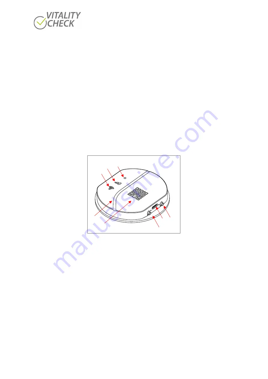
The base of the V I T A L I T Y C H E C K
is shown in (
). The base consists of an On/Off button (1), a
connectivity button (3), the USB-C socket (2), the sensor area (8) and several indicators (4, 5, 6).
•
On/Off button (1): power on when pressing, hold pressed to force power off.
•
USB-C socket (2) to charge the scanner.
•
Connectivity button (3): hold pressed to enter initialization mode. More details see chapter 10.1
•
The status indicator (4): multicolor LED. Please see chapter 12 for details.
•
Progress indicator (5): To indicate the progress of the measurement the progress indicator (6)
consists of three symbols and lights up in green while measuring. The three symbols will switch
on one after the other until all symbols lit. When the measurement is finished the light will be
switched off. More details please see chapter 12.
•
The WIFI indicator (6) light up in green and shows the device connectivity status. More details
please see chapter 12.
•
Groove (7) to align the hand when measuring.
•
When measuring the LEDs of the Sensor area (9) will switched on one after the other
Figure 2
To indicate a present status, the LED of the status indicator (4) shows the following colors:
•
Red color:
error or problem
•
Blue color:
In this mode the scanner opens a WIFI network (see chapter 10.1).
•
Cyan color: update mode
•
White:
USB connected, disconnect USB to enter measurement mode
The progress indicator (5) shows the progress. The displayed information has different meaning for
every status. See chapter 12 for more information.
4
6
5
8
7
1
2
3
Содержание VITALITY CHECK MSRRS SCN05
Страница 1: ...User Manual...


