


32
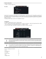
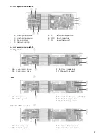
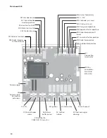
External expansion module
541
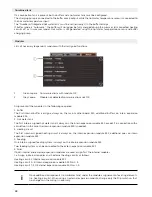
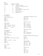
External modules are numbered in progressively increasing order during configuration (1-16). The dip switches must
be set accordingly.
0 - invalid
1
2
3
(Delivery condition)
230 V AC 3-pole
CAN Bus
X14 Input
X15 Output (if not used:
150
Ω
termination resistor)
X1 Power supply
X2 Power to next module,
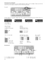
X4, X6
GND
N
L
CAN B (High)
CAN A (Low)
230 V AC mixer 4-pole
X12 Remote room sensor
“RTF H11” 3-pole (optional)
X12 Circulation
temperature
X5
GND
N
L (mixer close)
L (mixer open/
circulation pump)
3
2
1
Expansion Remote
module
room sensor
(external)
GND
free
Input
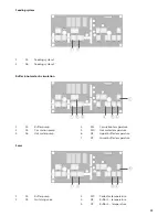
Heating circuit
1 X4 Heating circuit pump
3 X12 Room thermostat
2 X5 Heating circuit mixer
4 X9
Flow temperature
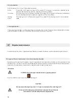
The CAN-bus wiring should be run using shielded twisted-pair cables (Cat5 or 6 shielded). Please ensure that the
shield of the cable is properly earthed to minimise interface along the cable.
Dip switch:
Dip switch
Содержание Top Light Zero 18
Страница 38: ...38 08 Notes ...
Страница 39: ......


