


28
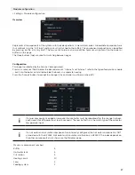
Combined tank
If a combination tank is present, both a buffer and a hot water tank must be configured.
The charging pump is connected to the buffer pump output, while the hot water temperature sensor is connected to
the hot water temperature input.
The "Number of integrated hot water tank" must be set (normally 1) in the buffer settings.
If buffer mode is "Automatic", the buffer will no longer be fully charged during the summer (all connected heating
circuits off or in summer mode). Hot water is still generated using the hot water temperature sensor and buffer
charging pump.
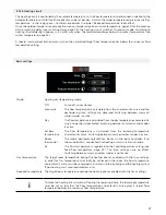
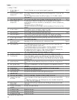
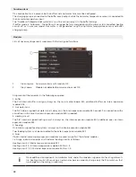
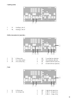
Modules
Lists all necessary (expansion) modules with their assigned functions.
1
Green square Communications with module OK
2
Grey square
Module not detected/communications not OK
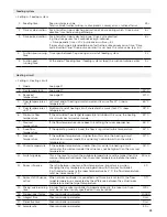
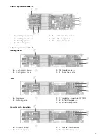
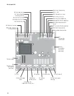
Assignment of the modules in the following sequence:
1. Buffer
The first internal buffer is assigne always on the main mother board 524, additional buffers on intern expansion
module 533.
2. Hot water tank
The first intern assigned hot water tank is always on the intern expansion module 532, except if in connection with a
circulation (in this case the intern expansion module 533 is needed).
3. Heating circuit
The first intern asssigned heating circuit is always on the intern expansion module 532, additional ones on intern
expansion module 533
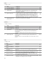
4. Feeding
One intern assigned feeding system is always on the intern expansion module 532
Two feeding systems can be connected to the extern expansion module 541
5. Solar
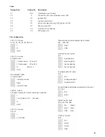
If both internal and external expansion modules are used, assign first the internal modules
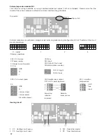
I.e. Assign 6 internal modules and 4 external heating circuits as follows:
Heating circuit 1: Internal expansion module 532
Heating circuit 2–6: Internal expansion module 533 No. 1–5
Heating circuit 7–10: External expansion module 541 No. 1–4
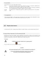
i
Move additional components (i.e. Hotwater tank) under the module assignement of existing elements
(i.e. heating circuits). When using an external expansion module, change only the Dip switch so that
no changes on the wiring is necessary.
Содержание Top Light Zero 18
Страница 38: ...38 08 Notes ...
Страница 39: ......


