9
5.0
Operation of Transtacker
5.1 Attachment to the Tractor
5.1.1 Tractor Requirements
PTO speed requirement is 540RPM.
Electrical requirements; 12V DC Supply and 1 hydraulic spool with the flow set low (approx. 20% of
flow) for pickup height adjustment.
The drawbar load capacity requires a minimum of 3 tonnes.
The recommended minimum horsepower of the tractor is 150HP.
Recommended minimum tractor weight is 6 tonnes.
The drawbar is normally supplied with a ring hitch, which is suitable for connection to pick up hitches
found on most tractors in the UK. Ensure that the tractor hitch is suitable for the dimension of the
ring.
5.1.2
Attachment to Tractor
•
Hitch the tractor to the machine, removing the drawbar stand and pin and placing in the
drawbar store. The machine should now sit approximately level at the chassis.
•
Install the PTO, ensuring the PTO guard chains are connected. Any damage caused to the
machine by ill-maintained guards is the operator
’s responsibility.
•
Connect the chosen method of braking, either hydraulic or air, and the two hydraulic hoses
for controlling the pickup height. The two pipes need to be connected as a pair.
•
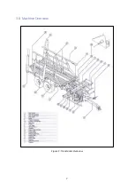
Release the Transtacker handbrake as shown in the top right corner of Figure 1, which is
under the front left of the chassis.
•
Ensure the tractor’s lights are 12V DC before connecting the machine’s lights via the 7
-pin
plug.
NOTE
: Rear Beacon lights come on with the trailer’s side lights.
Once installed, turn the tractor cautiously initially and ensure the tractor links, etc. do not make
contract with any part of the Transtacker and that there is sufficient clearance for the hoses and PTO.
It is advised to remove link arms where practical.
NOTE
: Any damage caused by the link arms is the operator
’s responsibility
.
5.2 Electrical
5.2.1 Mounting of the Control Box
•
Mount the screen and joystick in the tractor cab in a position that is convenient and
comfortable for the operator. The screen and joystick come with ram mount balls for quick
mounting/removal.
•
Ensure that the screen and joystick do not obstruct access to any of the important controls
within the tractor.
5.2.2 Connecting the Control Harness
•
The provided control harness connects the battery, screen, joystick and the tool post on
the Transtacker. The location of each connector should be labelled on the harness.
Содержание Transtacker
Страница 7: ...7 3 0 Machine Overview Figure 1 Transtacker Overview...
Страница 43: ...43 Figure 59 Auto Settings Screen...
Страница 57: ...57 8 1 Auto Pickup Sequence Figure 69 Auto Pickup Diagram...
Страница 58: ...58 8 2 Auto Stack Sequence both with and without tie Figure 70 Auto Stack Diagram...
Страница 59: ...59 8 3 Auto Lower Turntable Figure 71 Auto Lower Turntable Diagram...
Страница 60: ...60 8 4 Auto Open Sequence Figure 72 Auto Open Diagram...
Страница 61: ...61 8 5 Auto Tip Bed Down Sequence Figure 73 Auto Tip Bed Down Diagram...
Страница 62: ...62 8 6 Road Mode Sequence Figure 74 Road Mode Diagram...


