


- 52 -
INST
ALLA
TION
INSTALLATION
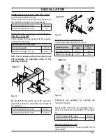
relevant cable clamps "P" (Fig. 6.18).
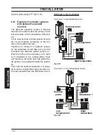
6.16
Example of hydraulic
systems
with hydraulic separator
(optional)
The hydraulic separator creates a reduced
load loss zone that renders the primary circuit
and secondary circuit hydraulically independ
-
ent.
In this case the flow rate that passes through
the circuits depends exclusively on the fea
-
tures of the pumps flow rate.
Therefore, by means of a hydraulic separa
-
tor, the secondary circuit's flow rate is put into
circulation only when the relative pump is on.
When the pump of the secondary is off, there
is no circulation in the corresponding circuit
and therefore, the entire flow rate pushed by
the primary is by-passed through the separa
-
tor.
Thus, with the hydraulic separator, it is possi
-
ble to have a constant flow rate production cir
-
cuit and a variable flow rate distribution circuit.
Hydraulic system
examples
Top zone + low temperature zone.
Fig. 6.33
S
Low temperature
Hight temperature
External probe
Top zone + 2 low temperature zones.
Fig. 6.34
S
Low
temperature 1
Low
temperature 2
Hight
temperature
External
probe


