


- 25 -
INST
ALLA
TION
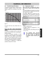
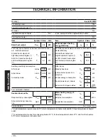
TECHNICAL INFORMATION
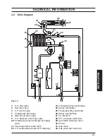
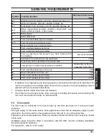
4.2 Main diagram
Fig. 4.2
3
C.H. flow valve
4
Gas inlet valve
5
C.H. return valve
7
Condensate drain pipe
8
Main circuit drain valve
9
C.H. pressure relief valve pipe
20
Condensing heat exchanger air purger
valve
21
Flue temperature probe NTC
22
C.H. temperature probe NTC (delivery)
23
Condensing heat exchanger
24
Safety thermostat
25
Flame-detecting electrode
26
Safety thermal fuse
27
Air manifold
28
C.H. pressure relief valve
29
Automatic airpurger valve
30
Pump
31
Gas valve
32
Gas valve inlet test point
41
42
43
23
25
38
39
36
31
40
30
34
28
4
5
8
7
3
35
32
29
22
44
21
24
26
45
20


