


- 27 -
INST
ALLA
TION
TECHNICAL INFORMATION
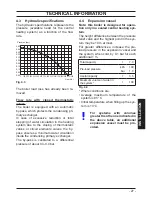
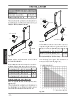
4.3
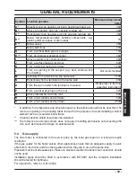
Hydraulic specifications
The hydraulic specifications represents the
pressure (available head for the central
heating system) as a function of the flow
rate.
Fig. 4.3
0 100 200 300 400 500 600 700 800 900 1000 1100 1200 1300 1400 1500
0,00
0,05
0,10
0,15
0,20
0,25
0,30
0,35
0,40
0,45
0,50
Pression (bar)
Flow (l/h)
The boiler load loss has already been re
-
moved.
Flow rate with closed thermostatic
valves
The boiler is equipped with an automatic
by-pass, which protects the condensing pri
-
mary exchanger.
In case of excessive reduction or total
stopping of water circulation in the
heating
system due to the closing of thermostatic
valves or circuit elements valves, the by-
pass ensures a minimum water circulation
inside the condensing primary exchanger.
The by-pass is calibrated to a differential
pressure of about 0.3-0.4 bar.
4.4
Expansion vessel
Note: this boiler is designed for opera-
tion only in a sealed central heating sys-
tem.
The height difference between the pressure
relief valve and the highest point in the sys
-
tem may be 10 m at most.
For greater differences, increase the pre-
load pressure in the expansion vessel and
the system, when cold, by 0.1 bar for each
additional 1 m.
Fig. 4.4
Total capacity
l
7.0
Pre-load pressure
kPa
100
bar
1.0
Useful capacity
l
3.5
Maximum volume of water in
the system *
l
109
* Where conditions are:
•
Average maximum temperature of the
system is 85 °C
•
Initial temperature when filling up the sys
-
tem is 10 °C
For systems with volumes
greater then the one indicated in
the above table, an additional
expansion vessel must be pro
-
vided.


