


- 42 -
INST
ALLA
TION
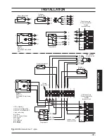
INSTALLATION
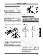
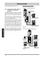
Coaxial Ø 60/100 mm (b) + vertical part
Ø 60 mm (a)
Telescopic coaxial flue
0.45-0.95 m
Maximum length (a + b)
15 m
This kit allows the products of combustion to
be discharged at a different location to the air
intake to avoid nuisance issues
.
Fig. 6.10
90°=---1 m
45°=---0,5 m
90°=---0,85 m
45°=---0,65 m
ø 60 mm
ø 60/100 mm
60 mm elbows and extensions can be added
to the vertical section.
Each additional elbow reduces the overall ac
-
ceptable length of the flue system as follows:
For the bend of 45° (60/100 mm) loss 0.5 m
For the bend of 90° (60/100 mm) loss
1 m
For the bend of 45° (60 mm) loss
0.65 m
For the bend of 90° (60 mm) loss
0.85 m
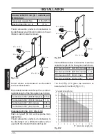
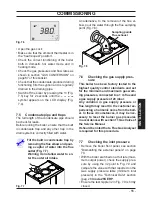
Pluming kit B (Fig. 6.11) (Fig. 6.12)
Push on type Ø 60 mm vertical plume man
-
agement kit
This kit allows the products of combustion to
be discharged at a different location, when
used with the standard horizontal flue kit.
Fig. 6.11
90°=---1 m
=---0,5 m
45°
90°=---0,85 m
45°=---0,65 m
ø 60 mm
ø 60/100 mm
Each additional elbow reduces the overall ac
-
ceptable length of the flue system as follows:
For the bend of 45° (60/100 mm) loss 0.5 m
For the bend of 90° (60/100 mm) loss
1 m
For the bend of 45° (60 mm) loss
0.65 m
For the bend of 90° (60 mm) loss
0.85 m
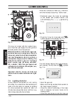
The chart Fig. 6.12 gives the maximum al
-
lowed value for
a + b
of (Fig. 6.11).
Fig. 6.12
”a” vertical length (m)
”b” horizontal length (m)
0
1
2
3
4
5
6
7
8
9
10
11
0
1
2
3
4
5
6
7
8
9
10 11
Allowed values
o d
u


