Biasi 41-583-30 Скачать руководство пользователя страница 28

- 28 -

INST

ALLA

TION

TECHNICAL INFORMATION

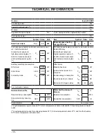
4.5  Technical data Inovia 25S ERP

Heat input

Nominal net 

(A)

 central heating

kW 

25,0

BTU/h

85304

Nominal gross

 (B) 

central heating

kW 

27,8

BTU/h 94687

Minimum net

 (A)

kW 

6,0

BTU/h 20473

Minimum gross

 (B)

kW 

6,7

BTU/h 22725

Useful output

Maximum

kW 

24,4

BTU/h

83256

Minimum

kW 

5,8

BTU/h 19790

Maximum condensing

kW 

26,6

BTU/h 90763

Minimum condensing

kW 

6,5

BTU/h 22179

Central heating

Min/Max flow temperature settings*

°C

25 - 85

Maximum pressure

kPa

250

bar

2,5

Minimum pressure

kPa

30

bar

0,3

Available head (in 1000 l/h)

kPa

23,0

bar

0,23

Seasonal efficiency G20

 (c)


%

88,8

Seasonal efficiency G31

 (c) 

%

89,8

* to the minimum useful output

(A)

 referred to the net calorific value at 15 °C and 

1013,25 mbar: G20 = 34,02 MJ/m

3

 - G31 = 46,34 MJ/

kg

(B)

 referred to the gross calorific value at 15 °C and 

1013,25 mbar: G20 = 37,78 MJ/m

3

 - G31 = 50,37 MJ/

kg

(C)

 The value is used in the UK Government’s Standard 

Assessment Procedure (SAP) for energy rating of 

dwellings. The test data from which it has been calcu

-

lated have been certified by a notified body.

(D)

 Values subject to tolerance

Gas supply pressures
Gas

Pa

mbar

Natural G20

Nom

2000

20

Min

1700

17

Max

2500

25

Propane G31

Nom

3700

37

Min

2500

25

Max

4500

45

Gas rate maximum

Natural G20

m

3

/h

2,67

Propane G31

kg/h

1,97

Gas rate minimum

Natural G20

m

3

/h

0,64

Propane G31

kg/h

0,47

Содержание 41-583-30

Страница 1: ...Wall hung fanflue roomsealed high efficiency gas boiler User manual and Installation instructions Inovia ERP Models G C Appl No Inovia 25S ERP 41 583 30 SYSTEM BOILER...

Страница 2: ...d hot water systems in the UK and to encourage regular servicing to optimise safety efficiency and performance Benchmark is managed and promoted by the Heating and Hot water Industry Council For more...

Страница 3: ...of complying with the appropriate Building Regulations England and Wales All installations must be notified to Local Area Building Control either directly or through a Competent Persons Scheme A Build...

Страница 4: ...patible with its performance and output can be used only for those purposes for which it has been specially designed must not be touched by children or by those unfamiliar with its operation must not...

Страница 5: ...abrasion In general normal handling and use will not present high risk Follow good hygiene practices wash hands before touching eyes consuming food drinking or using the toilet First aid Medical atte...

Страница 6: ...flush out the system both hot and cold in order to remove any system and installation debris to the British Standard BS 7593 code of practice It is also sensible to initially fire and commission the b...

Страница 7: ...upply pressure 55 7 7 Checking the inlet pressure 55 7 8 Lighting the boiler 56 7 9 Checking the ignition device 57 7 10 Checking the flue system 57 7 11 Checking the condensate drain pipe 57 7 12 Ins...

Страница 8: ...shown on the bottom of the boiler Fig 1 1 1 1 Controls panel 1 2 Isolation valves Fig 1 2 2 3 4 5 7 8 9 6 2 Gas supply label 3 C H flow valve 4 Gas inlet valve 5 C H return valve 6 Model and serial n...

Страница 9: ...imer 19 LCD display RESET that takes all parameters back to the factory value occurs only by setting parameter 08 04 Reset is displayed by switch on of all symbols present on the display Press keys 14...

Страница 10: ...day of the week is displayed high lighting the number with the following sequence 1 Mon 7 Sun Flashing solar circuit pump in operation Solar integration at the time of D H W withdrawal is indicat ed...

Страница 11: ...rostat Constantly illumi nated system anti freeze active SIGNAL DISPLAYED BY THE LCD LCD FUNCTION E01 Lack of burner ignition on safety lockout E02 Safety thermostat inter vention lockout E03 General...

Страница 12: ...0 15 P Pon 0 2 decreasing pressure critical 0 00 P 0 15 bar Pump activated for the post circulation phase Po flashing tempera ture flashing Boiler in anti freeze phase bP flashing temperature flashing...

Страница 13: ...W supply checking that the pressure indicated on the bottom part of the display Fig 2 2 In the case of incorrect pressure the value is visualised with a flashing symbol Fig 2 2 high pressure 2 8 bar...

Страница 14: ...the lower part of the boiler are open Fig 2 3 Fig 2 3 Open position Turn on the electricity supply to the boil er switching on the fused spur isolation switch The LCD display displays the state within...

Страница 15: ...play The heating flow set temperature and the symbol flash The background of the display is illuminated Fig 2 9 Fig 2 9 Adjusting the C H temperature WITH OUT the external temperature probe op tional...

Страница 16: ...second zone on the other hand is man aged independently from the remote so it already has its own time brackets N B In the case of a single zone controlled by TA and boiler clock where programmed wit...

Страница 17: ...d modify the time settings your new val ues will automatically over write the old ones providing you press the 13 and then 18 keys Emergency programmer reset To reset all time brackets press and hold...

Страница 18: ...for 2 seconds N B The following settings are also reset along with the time bracket Deactivation End of function The function programme will end when the time set passes in our example 1 day or when t...

Страница 19: ...the electricity supply to the boil er by means of the fused spur isolation switch Shut off the gas supply cock and the valves for the water circuits fitted under the boiler Fig 2 24 Fig 2 24 Close pos...

Страница 20: ...et cock If the boiler is deactivated have a qualified technician empty the boiler heating and domestic hot water circuit the C H system and the D H W system 3 3 Condensate drain The condensate drain m...

Страница 21: ...may occur even in case of a blockage of the condensate drainage e g plugged drain pipe It is advisable to check the condensate drainage pipe and traps for cleanness Press the reset key 14 on the boil...

Страница 22: ...gineer 3 7 Displaying in INFO mode The INFO mode allows the display of some information on the boiler functioning status In case of malfunctioning of the boiler it may be useful to communicate such in...

Страница 23: ...1 Safety thermostat lockout E02 General lockout E03 Lack of circulation pump E04 Faulty fan control system air pressure flue thermostat E05 Faulty C H temp probe NTC1 or NTC2 E06 Faulty external temp...

Страница 24: ...24 INSTALLATION TECHNICAL INFORMATION 4 TECHNICAL INFORMATION 4 1 Overview Fig 4 1 20 23 39 25 22 36 33 34 32 31 30 9 24 8 29 28 37 27 35 38 40 42 21 41 26...

Страница 25: ...sing heat exchanger air purger valve 21 Flue temperature probe NTC 22 C H temperature probe NTC delivery 23 Condensing heat exchanger 24 Safety thermostat 25 Flame detecting electrode 26 Safety therma...

Страница 26: ...nal block power supply terminal block external controls terminal block 34 Primary circuit pressure switch 35 Condensate trap 36 Fan 37 Air box air gas mixer 38 Ignition electrode 39 Burner 40 C H expa...

Страница 27: ...the by pass ensures a minimum water circulation inside the condensing primary exchanger The by pass is calibrated to a differential pressure of about 0 3 0 4 bar 4 4 Expansion vessel Note this boiler...

Страница 28: ...23 Seasonal efficiency G20 c 88 8 Seasonal efficiency G31 c 89 8 to the minimum useful output A referred to the net calorific value at 15 C and 1013 25 mbar G20 34 02 MJ m3 G31 46 34 MJ kg B referred...

Страница 29: ...A E kW 25 0 Exhaust temperature E C 83 1 Mass flow rate E kg s 0 0110 Flue gas figures Nominal heat input A E kW 25 0 CO2 content with gas G20 9 0 9 8 O2 content with gas G20 3 7 CO content with gas G...

Страница 30: ...heat output and low temperature regime 1 97 0 Auxiliary electricity consumption Other items At full load elmax 0 095 kW Standby heat loss Pstby 0 098 kW At part load elmin 0 010 kW Ignition burner po...

Страница 31: ...Regulations 5 1 Related documents The installation of this appliance must be in accordance with the relevant requirements of the current Gas Safe Installation Use Regulations the Local Building Regula...

Страница 32: ...into another room or space as an outhouse or lean to It is important that the position of the terminal allows a free passage of air across at all times The terminal should be located with due regard...

Страница 33: ...structure on the roof 600 Q Above intersection with the roof 600 R From a roof window and terminal 600 S From a roof window and terminal 2 500 In addition for temperature and structural reasons the t...

Страница 34: ...6798 2008 The schematic diagrams of possible connec tions are given in Fig 5 2 and Fig 5 3 The length of the condensate pipe should be kept to a minimum any external pipe should not be more than 3 m...

Страница 35: ...03 BSEN 14446 2004 the following notes are given for general guidance For Ireland IE refer to I S 813 2002 Pipework Copper tubing to BSEN 1057 is recommended for water pipes Jointing should be either...

Страница 36: ...flushed on completion to ensure flux residues swarf oils and other installation debris is removed Where a new boiler is fitted to an existing sys tem it is important the debris from the existing syste...

Страница 37: ...g from failure to comply with such provisions For Propane the appliance must also conform with the requirements of the distributors and comply with current Regulations and laws in force The safety rel...

Страница 38: ...lising gases present in the water We recommend the use of a suitable Build cert approved universal inhibitor to protect the C H system from corrosion Biasi UK strongly recommend that matched system ch...

Страница 39: ...ons Pipe sizes o d Gas C H return C H flow 22 mm Pressure relief valve 15 mm Condensate drain 25 mm rubber sizes in mm o d Condensate drained with 30 mm solvent weld pipe 6 6 Mounting the boiler Take...

Страница 40: ...SA A air intake S flue exhaust 6 8 Choice of flue The flue exhaust air intake can be installed in the mode C13 C33 C53 C63 The terminal must be higher than the boiler The following kits to be connecte...

Страница 41: ...es of the building EN 483 Fig 6 7 Type C13 Bends of 80 mm at 90 and at 45 are avail able that reduce the maximum total length of the pipes by For the bend of 45 loss 0 9 m For the bend of 90 loss 1 65...

Страница 42: ...5 60 mm loss 0 65 m For the bend of 90 60 mm loss 0 85 m Pluming kit B Fig 6 11 Fig 6 12 Push on type 60 mm vertical plume man agement kit This kit allows the products of combustion to be discharged a...

Страница 43: ...fused spur isolation switch to the power supply terminal block of the boiler Fig 6 16 keeping the same connec tions for the live brown wire and the neutral blue wire External 3A fuse or fused plug wi...

Страница 44: ...boiler by using the relevant cable clamps P Fig 6 18 Fig 6 18 P 6 10 Connecting the room thermo stat or zone valves Use the clamps indicated in Fig 6 16 to con nect the ambient thermostat Remove the e...

Страница 45: ...ed by the ambient thermostat Fig 6 22 N L V T Zone valve with micro contact Ambient Thermostat Potential free contacts of the zone valve micro switch Fig 6 23 N L V T Zone valve with micro contact Amb...

Страница 46: ...de livery temperature In order to achieve this setting it is necessary to enter into the programming load entry se quence scroll the various parameters us ing keys 16 or 17 Fig 6 25 until the letters...

Страница 47: ...al system switch 6 12 Connecting a system boiler to a cylinder Two schematic wiring diagrams are given in this section showing two possible ways to connect an external programmer to a mid position div...

Страница 48: ...ine The boiler operation is controlled by switching the mains supply In this case when the boiler is switched off some important features like the antifreeze system the monitoring of the boiler by the...

Страница 49: ...m thermostat A B 5 4 Cylinder thermostat C 1 2 8 7 6 GY WH OR GRYE BU 2 3 8 5 7 MAINS 230V a c Switched 3 Amp fused spur L N 2 3 1 Programmer HTG HW OFF HW ON L N 2 1 4 6 7 10 way junction box Valve c...

Страница 50: ...r HTG HW OFF HW ON L N Do not remove room thermostat link 10 way junction box Mid position diverter valve HTG Heating HW ON HotWaterON HW OFF HotWaterOFF Valve colour key WH White GRYE Green Yellow GY...

Страница 51: ...nnels to the voltage ones 230 V since they are powered at a safety low voltage and their maximum length must not exceed 20 meters Use the clamps indicated in Fig 6 32 to con nect the external probe Fi...

Страница 52: ...ondary circuit s flow rate is put into circulation only when the relative pump is on When the pump of the secondary is off there is no circulation in the corresponding circuit and therefore the entire...

Страница 53: ...2 7 2 Electrical installation Preliminary electrical system checks to en sure electrical safety shall be carried out by a competent person i e polarity earth continu ity resistance to earth and short...

Страница 54: ...ompleted turn on the C H system and run it until the temperature has reached the boiler operating temperature The system must then be immediately flushed through This procedure must be repeated twice...

Страница 55: ...Fig 7 7 An alternative to the removal of the flue el bow pour the water through the flue sampling point Fig 7 8 Fig 7 8 Sampling points Flue exhaust 7 6 Checking the gas supply pres sure This boiler...

Страница 56: ...rporate an anti cycling time delay It is normal when first switching the boiler on for the boiler to operate on heating for a few seconds then switch off After 3 4 minutes has elapsed the boiler will...

Страница 57: ...resent in the pipework After five consecutive resetting attempts the reset button is inhibited To restore its func tion it is necessary to switch the boiler off and on from the electrical mains using...

Страница 58: ...the function and use of the function selector Explain and demonstrate the function of time and temperature controls if fitted Explain how to turn off the appliance for both short and long periods and...

Страница 59: ...0 2 1 8 1 21 15 6 3 9 Press buttons and at the same time to enter the transparent programming Fig 8 2 Fig 8 2 Press buttons or to display the PM15 program that enables the external probe Fig 8 3 Fig 8...

Страница 60: ...re Fig 8 6 E g In order to have a flow temperature at the heating system of 60 C with an external tem perature of 5 C set a K at 1 5 sectioned line in Fig 8 6 Sequence for setting the K coefficient En...

Страница 61: ...10 5 0 5 10 15 20 25 30 40 50 60 70 80 15 C 15 C External temperature C K 1 5 The temperature trend when changing the setting made with keys 16 and 17 for a K 1 5 is shown in Fig 8 11 Sequence for set...

Страница 62: ...at parameter 11 Fig 8 16 has been activated Fig 8 16 It is possible to modify parameter 11 by 00 0s to 99 255s using keys 16 or 17 each increase or reduction by a unit on the display corresponds to 2...

Страница 63: ...al on off heating mode the minimum time between two ignitions is set at three minutes re ignition fre quency This time can be changed by a minimum of zero to a maximum of eight and a half min utes Ent...

Страница 64: ...n the programming of the REMOTE con trol to select a minimum time between two ig nitions when the boiler functions in normal on off heating mode Press button for more than 3 seconds to enter in mode F...

Страница 65: ...11 Max useful output in C H mode P 12 C H pump working type P 13 PARAMETER DIGIT VALUES Ignition power P 14 K value external probe diagram P 15 Regulation of the mini mum heating power P 16 D H W bur...

Страница 66: ...10 or 11 to change the value and confirm the value of the parameter with key 13 Press keys 16 or 17 Fig 8 31 to exit with out changing the value Repeat all the above setting sequences in order to vis...

Страница 67: ...C remove the fixing fork A and remove the pipe B Fig 9 1 Fig 9 1 A B C Carry out gas conversion by correctly re placing the gas restrictor Fig 9 2 refer ring to the Technical Data section pag 28 Inov...

Страница 68: ...h out changing the value Exiting the programming mode is au tomatic after 15 minutes or by cutting power Calibrate the gas valve according to the instructions given in the Service manual section Gas v...

Страница 69: ...lead dangerous voltage inside the appliance as well Ensure they are isolated In case of doubt turn off the gen eral system switch The Engineer should complete the Service Interval Record at the back...

Страница 70: ...only in the info section under value J15 N B The flashing symbol in Fig 10 5 is not an error The boiler continues to run normally but it indicates the expiry of the maintenance period Fig 10 5 10 3 D...

Страница 71: ...he case panel D down and in until completely held in place Fig 10 8 step 1 2 Repeat the same operation on the opposite side of the front panel D Fig 10 8 step 3 4 Ensure that the front panel edge is c...

Страница 72: ...primary circuit loose the condensing heat exchanger air purger valve 20 in Fig 10 12 Fig 10 12 20 10 6 Cleaning the condensing prima ry exchanger and the burner Removing the fan burner unit 39 in Fig...

Страница 73: ...ned electrode come into contact with the condensate water present within the combustion chamber it sends the boiler into safety lockout Therefore should the insulation be wet or deteriorated pro vide...

Страница 74: ...call an approved Ser vice Engineer 10 9 Combustion analysis check Carry out performance checks at the intervals provided by the laws in force Connect a flue analyser to the flue analysis outlets on th...

Страница 75: ...al pressures as described in section Checking the gas supply pressure on page 55 of this manual 10 13 Water inhibitor concentration Where chemical products are used the level of water treatment should...

Страница 76: ...water temperature i e 32 we are in the flue sweep function at the minimum power during heating Fig 10 23 Fig 10 23 Flue sweep function at maximum output in heating mode Press key 17 to vary the output...

Страница 77: ...ly set boiler status Fig 10 26 Fig 10 26 Winter Summer Note to service engineers It is required that the burner seal lip seal and mixing chamber seal along with the flame detection electrode are inspe...

Страница 78: ...nstigate the boiler guarantee the boiler needs to be registered with the manufacturer within one month of the installation To maintain the boiler guarantee it is essential that the boiler is serviced...

Страница 79: ...terlock Provided ALL SYSTEMS The system has been flushed and cleaned in accordance with BS7593 and boiler manufacturer s instructions Yes What system cleaner was used What inhibitor was used Quantity...

Страница 80: ...gister No Record At max rate CO ppm AND CO At min rate Where Possible CO ppm AND CO Comments Signature SERVICE 04 Date Engineer name Company name Telephone No Gas safe register No Record At max rate C...

Страница 81: ...81 NOTES...

Страница 82: ...82 NOTES...

Страница 83: ......

Страница 84: ...1796221983 17962 2198 3 0318 84A5 UK Biasi UK Ltd Commercial Road Leamore Enterprise Park WALSALL WS2 7NQ Sales Tel 01922 714600 Tech Service Tel 01922 714636 www biasi co uk 22 01 2018 N...

Отзывы: