Chapter 6 – Parameter Description [APP]
6-69
APP-40~APP-72: MMC Operation Control
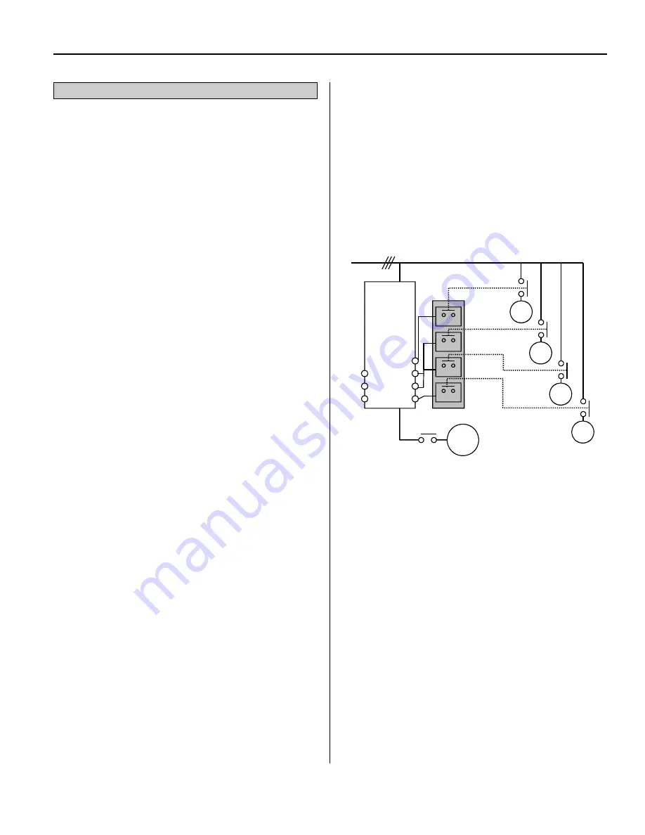
Multiple Motor Control
[MMC]:
The ‘PID’ control should be selected in
APP-02 to use this function.
One drive can control multiple motors. This
function is often used when controlling the flow rate
or pressure of fans or pumps. The built-in PI
controller directly controls a drive connected motor
after receiving process control feedback value and
keeps the control value constant by adjusting the
speed of the drive connected motor and connecting
and removing auxiliary motors to and from the
commercial line when needed.
In the case that the flow rate or flow pressure is
beyond or below the reference and the drive
connected motor cannot achieve the desired set point
by itself, auxiliary motors are automatically turned on
or off. A maximum of four (Aux.1-4 output) auxiliary
motors can be controlled. Each motors Starting and
Stopping Frequency can be set to automatically run
four auxiliary motors.
Auto Change
can be selected (APP-66) to
automatically switch the order of the running motors
for balancing motor run-time. Set to AUX_EXCH
mode for automatic changing of auxiliary motors
only and set to MAIN_EXCH mode for automatic
changing of all motors including main motor. For
MAIN_EXCH mode APP-67/68 should be set and
external sequence (APP-66) should be configured.
A malfunctioning motor can be skipped from
running by programming the multi-function input
terminals (M1, M2, M3, and M4) as Interlock1
Interlock4. If a programmed multi-function terminal
(M1, M2, M3 and M4) is opened (tripped), the drive
stops all running motors and restarts operation with
only the normal motors and leaves the malfunctioning
motor off. (Refer to APP-69)
Sleep function is initiated when demand is low.
The drive stops the motor when the motor runs below
the Sleep Frequency after the Sleep Delay Time has
expired. While in the sleep state, the drive continues
monitoring the input (feedback) and initiates a Wake-
Up function when the feedback has decreased below
the Wake-Up level (APP-65).
Note: Up to 4 auxiliary motors can be connected
to the AUX terminals on the control board
terminal strip.
MMC Diagram
See Parameter Descriptions for MMC Control on the
following pages
V1
V1S
I
M
M
M
M
M
SG
Line
Power
Main Motor
Aux. Motor 4
Aux. Motor 3
Aux. Motor 2
Aux. Motor 1
RLY1
RLY2
RLY3
RLY4
Aux1
Aux 2
Aux 3
Aux 4
Содержание RSi SG Series
Страница 10: ......
Страница 35: ...Notes...
Страница 36: ......
Страница 56: ...3 1 Notes...
Страница 65: ...Notes...
Страница 66: ......
Страница 87: ...Notes...
Страница 88: ......
Страница 96: ...6 8 NOTES...
Страница 112: ...6 24 NOTES...
Страница 148: ...6 60 NOTES...
Страница 172: ......
Страница 188: ...Notes...
Страница 198: ...Notes...
Страница 212: ...iv...
Страница 217: ......


