


GUIDE TO INSTALLATION AND OPERATION
MDX-3901 |
17
Section 1.
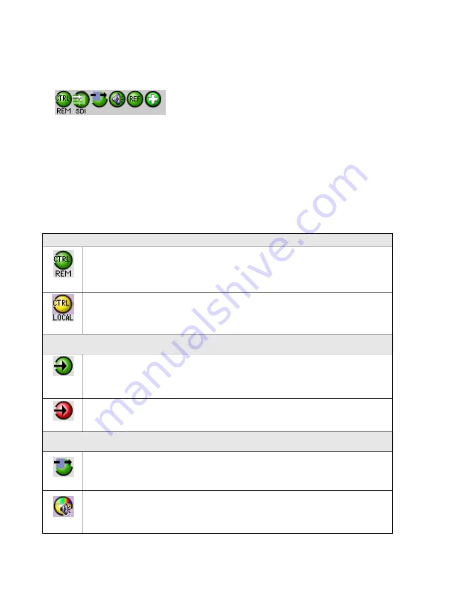
The top section displays six icons on the left. These icons report different statuses such as card
communication status, input signal and reference signal format and statuses. In some instances, they relate to
conditions defined through parameters settings.
Icon # 1
2
3
4
5
6
Move the mouse over an icon and a status message appears below the icon providing additional information.
If there is an error, the error status message appears in the message area without mouse-over.
If there are multiple errors, the error messages cycle so all can be seen
The icon whose status or error message is shown is highlighted with a mauve background
The table below describes the various status icons that can appear, and how they are to be interpreted.
In cases where there is more than one possible interpretation, read the error message in the iControl window to
see which applies.
Table
–iControl Status Icon interpretation
Icon #1
– Manual Card Configuration
(green)
Remote card control activated. The iControl interface can be used to operate the card
(yellow)
Local card control active, The card is being controlled using the Densité frame control
panel, as described in section 0. Any changes made using the iControl interface will have
no effect on the card.
Icon #2
– SDI Input status
(green)
Signal detected and valid.
Beneath the icon, the format will be indicated as 12G, Quad Link 3G, 3G or HD
and the specific format details will be listed if the cursor is moved over the icon.
(red)
Signal absent, No rear, Reference mismatch, Video/TRS error
Icon #3
– Operation Mode
(green)
Operation mode: process
– normal processing of the input signal
(yellow)
Operation mode: TEST
– color bar and audio test tones enabled (
see Section 5.8


