background image

DRYPOINT RA 200 – 2500 NA 

Dear Customer, 
thank you for choosing our product. In order to get the best performances out of this  product, please read this manual 
carefully. 
To avoid incorrect operation of the equipment and possible physical risk to the operator, please read and strictly follow 
the instructions contained in this manual. 
Note, these instructions are in addition to the safety rules that apply in the country where the dryer is installed. Before 
packing  for  shipment  each  DRYPOINT  RA  NA  series  refrigerated  air  dryer  undergoes  a  rigorous  test  to  ensure  the 
absence of any manufacturing faults and to demonstrate that the device can perform all the functions for which it has 
been designed. 
Once the dryer has been properly installed according to the instructions in this manual, it will be ready for use without 
any  further  adjustment.  The  operation  is  fully  automatic,  and  the  maintenance  is  limited  to  few  controls  and  some 
cleaning operations, as detailed in the following chapters. 
This manual must be maintained available in any moment for future references and it has to be intended as inherent 
part of the relevant dryer. 
Due  to  the  continuous  technical  evolution,  we  reserve  the  right  to  introduce  any  necessary  change  without  giving 
previous notice. 
Should you experience any trouble, or for further information, please do not hesitate to contact us. 
 

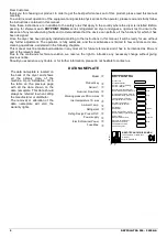
DATA NAMEPLATE 

Model 


Product key 


Serial n°. 


Nominal Flow Rate 


Working pressure PS min/max 


Inlet temperature TS max 


Ambient Temp. 


Refrigerant 


Refrig. Design Pres. HP/LP 


Power supply 


Electric Nominal Power 


Fuse Max. 


The  data  nameplate  is  located  on 
the  back  of  the  dryer  and  shows 
all  the  primary  data  of  the 
machine.  Upon  installation,  fill  in 
the  table  on  the  previous  page 
with  all  the  data  shown  on  the 
data  nameplate.  This  data  should 
always be referred to when calling 
the manufacturer or distributor.  
The  removal  or  alteration  of  the 
data  nameplate  will  void  the 
warranty rights. 


Produktschlüssel:

Product key:

Serial n° / year of building:
Serienr. / Baujahr:

Nominal flow rate (ISO1217):

scfm

Working pressure PS min/max:

Nemmvolumenstrom (ISO1217):

Betriebsüberdruck PS min/max:

psig

Inlet temperature TS max:
Eintrittstemperatur TS max:

°F

Ambient Temperature:

Umgebungstemperatur:

°F

Refrigerant:
Kältemittel:

type/oz

Refrig. Design Pres. HP/LP:
Kältem. Auslegungsdruck HD/ND:

psig

Power supply:
Elektrischer Anschluß:

V/ph/Hz

Electric Nominal Power:
Elektrische Leistung:

W/A

Fuse protection max:

Absicherung max:

A

DRYPOINT RA

BEKO TECHNOLOGIES GMBH

Im Taubental 7, 41468 Neuss
Germany
http:// www.beko.de

T

A

D

0

0

1

1


Содержание DRYPOINT RA 1000/AC NA

Страница 1: ...EN Operating manual Maintenance manual Spare parts Refrigerating air dryer DRYPOINT DRYPOINT DRYPOINT DRYPOINT RA RA RA RA 200 200 200 200 250 250 250 2500 0 0 0 NA NA NA NA ...

Страница 2: ...lution we reserve the right to introduce any necessary change without giving previous notice Should you experience any trouble or for further information please do not hesitate to contact us DATA NAMEPLATE Model Product key Serial n Nominal Flow Rate Working pressure PS min max Inlet temperature TS max Ambient Temp Refrigerant Refrig Design Pres HP LP Power supply Electric Nominal Power Fuse Max T...

Страница 3: ... 20 5 10 Capillary Tube 20 5 11 Alu Dry Module 20 5 12 Hot Gas By pass Valve 20 5 13 Refrigerant Pressure Switches PA PB PV 21 5 14 Safety thermo switch Ts 21 5 15 Compressor crankcase heater DRYPOINT RA 600 2500 NA 21 5 16 DMC14 Electronic Instrument Air Dryer Controller 22 5 17 Electronic level controlled condensate drain BEKOMAT 23 6 Maintenance troubleshooting spares and dismantling 24 6 1 Con...

Страница 4: ... Electrical Diagram DRYPOINT RA 200 500 NA R 460 1 60 42 7 3 3 Electrical Diagram DRYPOINT RA 200 500 NA R 460 1 60 43 7 3 4 Electrical Diagram DRYPOINT RA 200 500 NA R 460 1 60 44 7 3 5 Electrical Diagram DRYPOINT RA 600 1250 NA R 460 1 60 45 7 3 6 Electrical Diagram DRYPOINT RA 600 1250 NA R 460 1 60 46 7 3 7 Electrical Diagram DRYPOINT RA 600 1250 NA R 460 1 60 47 7 3 8 Electrical Diagram DRYPO...

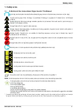
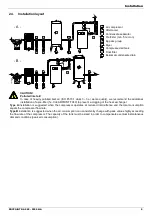
Страница 5: ...els removed Maintenance or control operation to be performed by qualified personnel only 1 ARIA AIR LUFT AIR Compressed air inlet connection point ARIA AIR LUFT AIR Compressed air outlet connection point Condensate drain connection point Cooling water inlet connection point Water Cooled Cooling water outlet connection point Water Cooled Operations which can be performed by the operator of the mach...

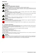
Страница 6: ...it damaged by accident modification misuse negligence or misapplication Unauthorized alterations will immediately void the warranty In case of fire use an approved fire extinguisher water is not an acceptable means in cases of electrical fire 1 3 Proper Use of the Dryer This dryer has been designed manufactured and tested for the purpose of separating the humidity normally contained in compressed ...

Страница 7: ...tated on the manufacturer s data nameplate must not be exceeded Prior to use the user must fit safety pressure relief devices 7 All documentation supplied with the equipment manual declaration of conformity etc must be kept for future reference 8 Do not apply weights or external loads on the vessel or its connecting piping Articolo I WARNING Unauthorized interference Users of the equipment must co...

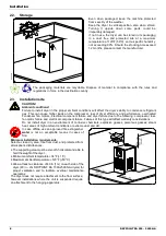
Страница 8: ...ted condenser fan motors electrical component failure and dryer failure due to the following compressor loss fan motor failure and electrical component failure Failures of this type will affect warranty considerations Do not install dryer in an environment of corrosive chemicals explosive gasses poisonous gasses steam heat areas of high ambient conditions or extreme dust and dirt In case of fire u...

Страница 9: ...73 1 class 3 3 or worse quality we recommend the additional installation of a pre filter f e CLEARPOINT F040 to prevent a clogging of the heat exchanger Type A installation is suggested when the compressor operates at reduced intermittence and the total consumption equals the compressor flow rate Type B installation is suggested when the air consumption can consistently change with peak values hig...

Страница 10: ...ir flow rate Minimum Example Example An DRYPOINT RA 500 NA has a nominal duty of 500 scfm 849 m3 h What is the maximum allowable flow through the dryer under the following operating conditions Inlet air pressure 120 psig 8 barg Ambient temperature 105 F 40 C Inlet air temperature 105 F 40 C Pressure DewPoint 38 F 3 C Each item of data has a corresponding numerical factor as follows The procedure h...

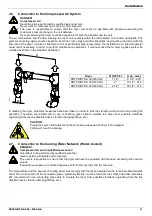
Страница 11: ...YPOINT RA 400 500 NA 2 1 2 16 1 8 410 Ø BPY0001 In realising the dryer particular measures have been taken in order to limit the vibration which could occur during the operation Therefore we recommend to use connecting pipes able to insulate the dryer from possible vibrations originating from the line flexible hoses vibration damping fittings etc CAUTION Piping the dryer inlet outlet connections m...

Страница 12: ...rain line towards anybody The dryer comes already fitted with an electronically level controlled BEKOMAT condensate drain Connect and properly fasten the condensate drain to a collecting plant or container The drain cannot be connected to pressurized systems Don t dispose the condensate in the environment The condensate collected in the dryer contains oil particles released in the air by the compr...

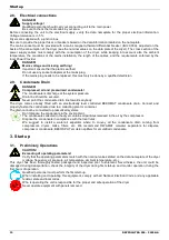
Страница 13: ...nstalled Check the piping for air leakage Ensure the drain is regularly cycling wait for its first interventions 3 3 Start up and shut down For short periods of inactivity max 2 3 days we recommend that power is maintained to the dryer and the control panel Otherwise before re starting the dryer it is necessary to wait at least 2 hours for the compressor crankcase heater to heat the oil of the com...

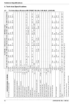
Страница 14: ...20 38 50 34 1 100 160 38 70 100 7 200 14 1 7 0 12 1 1 2 R404A 28 0 8 1500 2500 5 8 11200 460 3 60 1560 2 2 1710 2 5 70 139 63 scfm m3 h l min F C F C F C F C psig barg psig barg psi bar NPT F oz kg cfm m3 h HP Btu h US gpm m3 h F C psig barg NPT F V Ph Hz W A W A dbA lbs kg DRYPOINT RA NA R MODEL Air flow rate at nominal condition 1 Pressure DewPoint at nominal condition 1 Nominal max ambient temp...

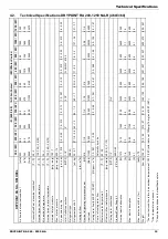
Страница 15: ... 1 100 160 38 70 100 7 200 14 1 7 0 12 1 1 2 R404A 25 0 7 5 8 11200 1 2 0 27 Automatic by valve 85 30 45 145 3 10 1 2 460 3 60 1270 1 8 1420 2 1 70 135 61 scfm m 3 h l min F C F C F C F C psig barg psig barg psi bar NPT F oz kg cfm m 3 h HP Btu h US gpm m 3 h F C psig barg NPT F V Ph Hz W A W A dbA lbs kg DRYPOINT RA NA R MODEL Air flow rate at nominal condition 1 Pressure DewPoint at nominal cond...

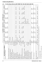
Страница 16: ... 19 FL ANSI 4 150 R404A 318 9 0 11200 19000 4 3 4 72800 460 3 60 8700 12 7 10000 14 5 80 1168 530 scfm m3 h l min F C F C F C F C psig barg psig barg psi bar NPT F oz kg cfm m3 h HP Btu h US gpm m3 h F C psig barg NPT F V Ph Hz W A W A dbA lbs kg DRYPOINT RA NA R MODEL Air flow rate at nominal condition 1 Pressure DewPoint at nominal condition 1 Nominal max ambient temperature Min ambient temperat...

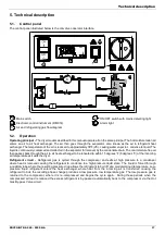
Страница 17: ... drain The cool moisture free air then passes back through the air to air heat exchanger to be reheated to within 15 degrees F 8 degre es C of the incoming air temperature as it exits the dryer Refrigerant circuit Refrigerant gas is cycled through the compressor and exits at high pressure to a condenser where heat is removed causing the refrigerant to condense to a high pressure liquid state The l...

Страница 18: ...n a Air to air heat exchanger 10 Filter Drier b Air to refrigerant exchanger 11 Capillary tube c Condensate separator 12 T1 Temperature probe DewPoint 2 Refrigerant pressure switch PB 13 Condensate drain isolation valve 3 Safety thermo switch TS 17 Air Dryer Controller 4 Refrigerant pressure switch PA 18 Condenser Water Cooled 5 Refrigerant Fan pressure switch PV 19 Condenser water regulating valv...

Страница 19: ...mpurities 5 7 Condenser Water Cooled The condenser is the component in which the gas coming from the compressor is cooled down and condensed becoming a liquid Basically it is a water refrigerating gas exchanger where the cooling water lowers the temperature of the refrigerating gas The temperature of the inlet water must not exceed the nominal values It must also guarantee an adequate flow and tha...

Страница 20: ...educed power requirements The generous dimensions of the air to refrigerant heat exchanger plus the counter flow gas flow allows full and complete evaporation of the refrigerant preventing liquid return to the compressor The high efficiency condensate separator is located within the heat exchanger module No maintenance is required and the coalescing effect results in a high degree of moisture sepa...

Страница 21: ...4 F To lerance 14 5 psi R 404 A Start 21 barg 47 C Stop 18 barg 40 C Tolera nce 1 bar PV2 DRYPOINT RA 1500 2500 NA Fan control pressure switch is placed at the discharge side of refrigeration compressor It keeps the condensation temperature pressure constant within preset limits Air Cooled High Speed Calibrated pressure R 404 A Start 334 psig 124 F Stop 297 psig 115 F T olerance 14 5 psi R 404 A S...

Страница 22: ... 8 9 please also see electric drawings into the attachments max 250V 1A min 5VDC 10mA with dryer off or in alarm conditions contact is open with dryer on and correct operating DewPoint contact is closed OPERATION After dryer starting the electronic controller displays current operating DewPoint it shows the measured temperature in Celsius degrees C with a 0 5 C resolution or in Fahrenheit degr ees...

Страница 23: ...nic control and a diaphragm solenoid valve will open to discharge the condensate Right in time the discharge line will be closed again without wasting compressed air ATTENTION These BEKOMAT condensate drains have been specially designed for the use in a refrigerant dryer DRYPOINT RA NA Any Installation in other compressed air treatment units or the exchange against a different drain brand may lead...

Страница 24: ...peration Avoid contact until system or component has dissipated heat DAILY Verify that the DewPoint displayed on the electronic instrument is correct Check the proper operation of the condensate drain systems Verify the condenser for cleanliness EVERY 200 HOURS OR MONTHLY With an air jet max 2 bar 30 psig blowing from inside towards outside clean the condenser repeat this operation blowing in the ...

Страница 25: ...re switch PA has been activated see specific point The low pressure switch PB has been activated see specific point The safety thermo switch TS has been activated see specific point The alarm led is ON see specific point If the compressor still doesn t work replace it The fan of the condenser doesn t work Air Cooled Verify the electric wiring PV PV1 PV2 pressure switch is faulty contact a refriger...

Страница 26: ...operation of the dryer 8 The TS thermo switch is faulty replace it The PA high pressure switch has been activated Check which of the following has caused the activation 1 The ambient temperature is too high or the room aeration is insufficient provide proper ventilation Air Cooled 2 The condenser is dirty clean it Air Cooled 3 The condenser fan doesn t work see specific point Air Cooled 4 The cool...

Страница 27: ...1 1 10 Filter drier XERA 6650 SSN 165 1 1 1 1 DewPoint probe T1 DMC14 XERA 5625 NNN 035 1 1 1 1 12 DewPoint probe T1 DMC14 XERA 5625 NNN 037 1 1 1 1 1 1 12 2 Extension for probe L 1200 XERA 5625 NNN 030 1 1 1 1 13 Condensate drain isolation valve XERA 6431 0MF 155 1 1 1 1 1 1 1 1 1 1 17 DMC14 Controller 230V XERA 5620 110 103 1 1 1 1 1 1 1 1 1 1 BEKOMAT 31 BM31 BI supply voltage 1 1 1 1 21 BEKOMAT...

Страница 28: ...e 2 2 2 2 22 Main switch XERA 5450 SZN 105 1 1 1 1 23 HP Refrigerant gauge high pressure XERA 5660 NNN 010 1 1 1 1 24 LP Refrigerant gauge low pressure XERA 5660 NNN 005 1 1 1 1 60 1 Q1 Circuit breaker XERA 5444 3SM 160 1 1 1 1 60 2 Q2 Auxiliary contact XERA 5444 3SM 145 1 1 1 1 Q3 Circuit breaker for transformer XERA 5444 3ST 020 1 1 1 1 60 3 Q4 Circuit breaker XERA 5444 1C6 006 1 1 1 1 60 4 Q1 Q...

Страница 29: ...gerant Chemical formula TLV GWP R134a HFC CH2FCF3 1000 ppm 1300 R404A HFC CH2FCF3 C2HF5 C2H3F3 1000 ppm 3784 6 5 Dismantling of the Dryer If the dryer is to be dismantled it has to be split into homogeneous groups of materials Part Material Refrigerant fluid R404A R134a Oil Canopy and Supports Carbon steel Epoxy paint Refrigerating compressor Steel Copper Aluminium Oil Alu Dry Module Aluminium Con...

Страница 30: ...List of attachments 30 DRYPOINT RA 200 2500 NA 7 List of attachments 7 1 Dryers Dimensions 7 1 1 Dryers Dimensions DRYPOINT RA 200 250 NA AC 7 1 2 Dryers Dimensions DRYPOINT RA 300 350 NA AC ...

Страница 31: ...List of attachments DRYPOINT RA 200 2500 NA 31 7 1 3 Dryers Dimensions DRYPOINT RA 400 500 NA AC 7 1 4 Dryers Dimensions DRYPOINT RA 600 1000 NA AC ...

Страница 32: ...List of attachments 32 DRYPOINT RA 200 2500 NA 7 1 5 Dryers Dimensions DRYPOINT RA 1250 NA AC 7 1 6 Dryers Dimensions DRYPOINT RA 1500 2000 NA AC 7 1 7 Dryers Dimensions DRYPOINT RA 2500 NA AC ...

Страница 33: ...List of attachments DRYPOINT RA 200 2500 NA 33 7 1 8 Dryers Dimensions DRYPOINT RA 200 250 NA WC 7 1 9 Dryers Dimensions DRYPOINT RA 300 350 NA WC ...

Страница 34: ...List of attachments 34 DRYPOINT RA 200 2500 NA 7 1 10 Dryers Dimensions DRYPOINT RA 400 500 NA WC 7 1 11 Dryers Dimensions DRYPOINT RA 600 1000 NA WC ...

Страница 35: ...List of attachments DRYPOINT RA 200 2500 NA 35 7 1 12 Dryers Dimensions DRYPOINT RA 1250 NA WC 7 1 13 Dryers Dimensions DRYPOINT RA 1500 2000 NA WC 7 1 14 Dryers Dimensions DRYPOINT RA 2500 NA WC ...

Страница 36: ...rigerant gauge low pressure 5 Refrigerant pressure switch fan PV 6 Refrigerating compressor 51 Front panel 7 Hot Gas By pass Valve 52 Back panel 8 Condenser Air Cooled 53 Right lateral panel 9 Condenser fan 54 Left lateral panel 9 1 Motor 55 Cover 9 2 Blade 56 Base plate 9 3 Grid 57 Upper plate 10 Filter Drier 58 Support beam 11 Capillary tube 59 Support bracket 12 T1 Temperature probe DewPoint 60...

Страница 37: ...List of attachments DRYPOINT RA 200 2500 NA 37 7 2 2 Exploded view DRYPOINT RA 200 350 NA ...

Страница 38: ...List of attachments 38 DRYPOINT RA 200 2500 NA 7 2 3 Exploded view DRYPOINT RA 400 500 NA ...

Страница 39: ...List of attachments DRYPOINT RA 200 2500 NA 39 7 2 4 Exploded view DRYPOINT RA 600 1250 NA ...

Страница 40: ...List of attachments 40 DRYPOINT RA 200 2500 NA 7 2 5 Exploded view DRYPOINT RA1500 2500 NA ...

Страница 41: ... side HIGH pressure PB Pressure switch Compressor suction side LOW pressure TS Safety thermo switch BOX Electric box ELD Bekomat drainer SEZ Main switch with door block P Start Stop button Power on light X Alarm on light R Compressor crankcase heater SD Door interlock safety switch CP Control panel NT1 Air Cooled only NT2 Verify transformer connection according to power supply voltage NT3 Jump if ...

Страница 42: ...cal Diagram DRYPOINT RA 200 500 NA R 460 1 60 0 1 3 2 4 5 6 7 8 9 Rev Drawing no Pag BEKO TECHNOLOGIES GMBH http www beko de TR OPTIONAL 3 575V 60Hz PE SUPPLY 3 460V 60Hz PE SEZ 0 1 3 TK U W M V 3 TV M U V 2 9 K 2 1 2 1 4 6 3 5 V 2 2 W A 2 9 TF Q3 4A Q1 Q2 B K V ...

Страница 43: ... 14 1 3 1 3 2 1 3 4 6 5 1 4 N U 1 3 2 1 4 1 4 4 K A2 A1 V A2 A1 P 5 A 2 9 9 PV 0 22 21 PR DEW POINT ALARM min 5VDC 10mA 2 5 4 max 250V 1A 8 9 12 11 Drawing no Pag Rev 4 9 12 1 8 5 2 1 2 7 X ON CP N Rd L TV 13 14 A P TS A 2 9 4 12 13 Q2 1 5 14 ON CP B P K 13 14 1 X2 Wh 14 X1 2 1 13 0 1 2 Air Dryer Controller 3 ON CP DMC14 3 4 5 6 7 8 Q1 1 3 14 13 9 ELD 14 13 P TK P PB PA ...

Страница 44: ...00 NA R 460 1 60 0 1 2 3 4 5 6 7 8 9 Pag http www beko de BEKO TECHNOLOGIES GMBH Drawing no Rev Q1 MOUNTING PLATE UKK 5 TERMINAL BN BROWN BK BLACK BU BLUE TV PB PA TK PV TF Q3 Q2 8 7 5 4 3 2 1 TERMINAL 6 12 26 WIRE TYPE 32 12 14 14 10 9 SEZ TS 22 24 K A V 9 10 7 8 5 6 1 2 3 4 DMC14 X P ELD ...

Страница 45: ...RYPOINT RA 600 1250 NA R 460 1 60 0 1 3 2 4 5 6 7 8 9 3 U W M V 3 TV M U V 2 9 K 2 1 2 1 4 6 3 5 V 2 2 W 2 9 Q1 Q2 Rev Drawing no Pag BEKO TECHNOLOGIES GMBH http www beko de K V KT 50 60Hz A B Q4 TF 2 1 12 K 11 Q3 A R TR OPTIONAL 3 575V 60Hz PE SUPPLY 3 460V 60Hz PE SEZ 0 1 ...

Страница 46: ... 14 1 9 12 1 3 1 3 2 1 3 4 6 5 1 4 11 N U 12 1 3 2 1 4 1 4 4 K A2 A1 V A2 A1 P 5 A 2 9 9 PV 0 22 21 PR DEW POINT ALARM min 5VDC 10mA 2 5 4 max 250V 1A 8 9 12 11 Drawing no Pag Rev 4 9 12 1 8 5 2 1 2 7 X ON CP N Rd L TV 13 14 A P TS A 2 9 4 12 13 Q2 1 5 14 ON CP B P K 13 14 1 X2 Wh 14 X1 2 1 13 0 1 2 Air Dryer Controller 3 ON CP DMC14 3 4 5 6 7 8 Q1 1 3 14 13 9 ELD PB P P PA ...

Страница 47: ...2 3 4 5 6 7 8 9 PV R PB PA TV 2 12 TERMINAL WIRE 1 15 TYPE TERMINAL UKK 5 5 3 4 26 12 6 7 23 22 14 14 11 8 10 9 32 S R R 12 12 S ELD Pag http www beko de BEKO TECHNOLOGIES GMBH Drawing no Rev C C 5 6 7 8 1 2 3 4 Q1 MOUNTING PLATE T1 11 12 9 10 Q4 Q2 Q3 K V TF A SEZ TS C C R S T T T UK6 N PR T1 white red T1 UKK 5 ...

Страница 48: ...A 1500 2500 NA R 460 1 60 0 1 3 2 4 5 6 7 8 9 Rev Drawing no Pag http www beko de BEKO TECHNOLOGIES GMBH K V 50 60Hz Q3 TF 4 6 2 OPTIONAL 3 575V 60Hz PE SUPPLY 3 460V 60Hz PE SEZ 0 1 Q1 W1 V1 U1 3 U W M V 2 9 W2 M 3 U2 V2 TV 2 9 V2 2 3 V1 2 2 2 1 K TR Q2 5 1 3 A R Q4 2 1 12 K B 11 A ...

Страница 49: ...12 2 4 6 5 11 12 1 3 2 4 V2 A2 A1 P PV2 P PV1 N L B 4 1 8 5 12 9 A 14 13 P TS ON CP X DMC14 ON CP Rd 14 K 2 1 13 A 2 9 9 5 0 22 21 P Wh X2 X1 ON CP 1 14 13 12 2 9 A 4 1 2 1 6 1 5 1 5 1 6 1 2 1 5 1 6 1 2 N U N U 1 9 2 1 2 7 2 1 14 1 5 13 Q2 13 14 1 2 Q1 PB P P PA 2 4 5 8 9 11 12 min 5VDC 10mA DEW POINT ALARM max 250V 1A Air Dryer Controller 3 POWER T1 PR TV http www beko de BEKO TECHNOLOGIES GMBH E...

Страница 50: ...RE SWITCH COMPRESSOR DISCHARGE HIGH SIDE SAFETY PRESSURE SWITCH FAN CONTROL PRESS SWITCH HIGH SPEED AIR COOLED ONLY AIR COOLED ONLY 2x BEKOMAT DRAINER COMPRESSOR SUCTION LOW SIDE max 250V 1A min 5VDC 10mA Q1 K SEZ A V2 V1 Q2 Q3 Q4 OPTIONAL TR TRANSFORMER 460V SIDE CONNECT TO SEZ FOR 3 460 60 POWER SUPPLY DEW POINT PROBE COMPRESSOR CRANKCASE HEATER R SD PV1 PA PB PV2 TV TS MOUNTING PLATE TF 7 8 5 6...

Страница 51: ...List of attachments DRYPOINT RA 200 2500 NA 51 ...

Страница 52: ...DRYPOINT RA 200 2500 NA_manual_en_2009 10 Subject to technical changes without prior notice errors not excluded ...

Отзывы: