Installation
DRYPOINT RA 200 – 2500 NA
9
2.4.
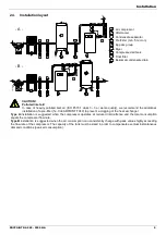
Installation layout
1
Air compressor
2
Aftercooler
3
Condensate separator
4
Pre-Filter (min. 5 micron)
5
By-pass group
6
Dryer
7
Compressed air tank
8
Final filter
9
Bekomat condensate drain
2
2
1
6
IN
OUT
7
- A -
- B -
1
7
5
6
IN
OUT
5
8
9
9
8
9
4
9
3
9
9
9
3
4
9
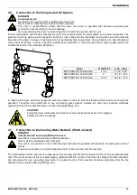
CAUTION!
Polluted inlet air!
In case of heavily polluted inlet air (ISO 8573.1 class 3.-.3 or worse quality), we recommend the additional
installation of a pre-filter (f.e. CLEARPOINT F040) to prevent a clogging of the heat exchanger
Type A installation is suggested when the compressor operates at reduced intermittence and the total consumption
equals the compressor flow rate.
Type B installation is suggested when the air consumption can consistently change with peak values highly exceeding
the flow rate of the compressor. The capacity of the tank must be sized in order to compensate eventual instantaneous
demand conditions (peak air consumption).
Содержание DRYPOINT RA 1000/AC NA
Страница 37: ...List of attachments DRYPOINT RA 200 2500 NA 37 7 2 2 Exploded view DRYPOINT RA 200 350 NA ...
Страница 38: ...List of attachments 38 DRYPOINT RA 200 2500 NA 7 2 3 Exploded view DRYPOINT RA 400 500 NA ...
Страница 39: ...List of attachments DRYPOINT RA 200 2500 NA 39 7 2 4 Exploded view DRYPOINT RA 600 1250 NA ...
Страница 40: ...List of attachments 40 DRYPOINT RA 200 2500 NA 7 2 5 Exploded view DRYPOINT RA1500 2500 NA ...
Страница 51: ...List of attachments DRYPOINT RA 200 2500 NA 51 ...

