


Index
DRYPOINT RA 200 – 2500 NA
3
1.
Safety rules.................................................................................................................................................... 5
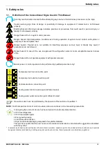
1.1.
Definition of the Conventional Signs Used in This Manual............................................................................ 5
1.2.
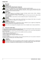
Warnings ....................................................................................................................................................... 6
1.3.
Proper Use of the Dryer................................................................................................................................. 6
1.4.
Instructions for the use of pressure equipment according to PED Directive 97/23/EC ................................. 7
2.
Installation ..................................................................................................................................................... 7
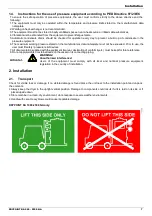
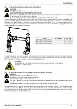
2.1.
Transport ....................................................................................................................................................... 7
2.2.
Storage .......................................................................................................................................................... 8
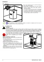
2.3.
Installation site ............................................................................................................................................... 8
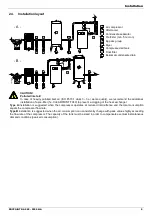
2.4.
Installation layout ........................................................................................................................................... 9
2.5.
Correction factors ........................................................................................................................................ 10
2.6.
Connection to the Compressed Air System ................................................................................................ 11
2.7.
Connection to the Cooling Water Network (Water-Cooled) ........................................................................ 11
2.8.
Electrical connections.................................................................................................................................. 12
2.9.
Condensate Drain........................................................................................................................................ 12
3.
Start up ........................................................................................................................................................ 12
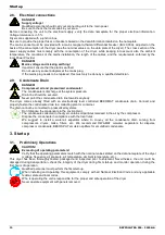
3.1.
Preliminary Operations ................................................................................................................................ 12
3.2.
First start-up ................................................................................................................................................ 13
3.3.
Start-up and shut down ............................................................................................................................... 13
4.
Technical Specifications .............................................................................................................................. 14
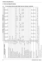
4.1.
Technical Specifications DRYPOINT RA 200-1250 NA-R (460/3/60)........................................................ 14
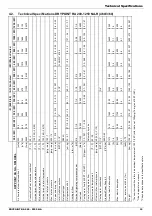
4.2.
Technical Specifications DRYPOINT RA 200-1250 NA-R (460/3/60)......................................................... 15
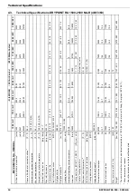
4.3.
Technical Specifications DRYPOINT RA 1500-2500 NA-R (460/3/60)....................................................... 16
5.
Technical description................................................................................................................................... 17
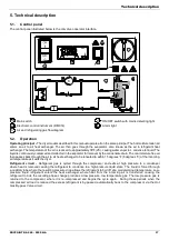
5.1.
Control panel ............................................................................................................................................... 17
5.2.
Operation..................................................................................................................................................... 17
5.3.
Flow Diagram (Air-Cooled) .......................................................................................................................... 18
5.4.
Flow Diagram (Water-Cooled)..................................................................................................................... 18
5.5.
Refrigerating compressor ........................................................................................................................... 19
5.6.
Condenser (Air-Cooled)............................................................................................................................... 19
5.7.
Condenser (Water-Cooled) ......................................................................................................................... 19
5.8.
Condenser water regulating valve (Water-Cooled) ..................................................................................... 19
5.9.
Filter Drier.................................................................................................................................................... 20
5.10.
Capillary Tube.............................................................................................................................................. 20
5.11.
Alu-Dry Module ............................................................................................................................................ 20
5.12.
Hot Gas By-pass Valve ............................................................................................................................... 20
5.13.
Refrigerant Pressure Switches P
A
-P
B
-P
V
..................................................................................................... 21
5.14.
Safety thermo-switch T
s
............................................................................................................................... 21
5.15.
Compressor crankcase heater (DRYPOINT RA 600-2500 NA).................................................................. 21
5.16.
DMC14 Electronic Instrument (Air Dryer Controller) ................................................................................... 22
5.17.
Electronic level controlled condensate drain BEKOMAT............................................................................. 23
6.
Maintenance, troubleshooting, spares and dismantling .............................................................................. 24
6.1.
Controls and Maintenance........................................................................................................................... 24
6.2.
Troubleshooting........................................................................................................................................... 25
6.3.
Spare Parts.................................................................................................................................................. 27
6.4.
Maintenance operation on the refrigerating circuit ..................................................................................... 29
6.5.
Dismantling of the Dryer .............................................................................................................................. 29
7.
List of attachments ...................................................................................................................................... 30
7.1.
Dryers Dimensions ...................................................................................................................................... 30
7.1.1.
Dryers Dimensions DRYPOINT RA 200-250 NA /AC ................................................................................. 30
7.1.2.
Dryers Dimensions DRYPOINT RA 300-350 NA /AC ................................................................................. 30
7.1.3.
Dryers Dimensions DRYPOINT RA 400-500 NA /AC ................................................................................. 31
7.1.4.
Dryers Dimensions DRYPOINT RA 600-1000 NA /AC ............................................................................... 31
7.1.5.
Dryers Dimensions DRYPOINT RA 1250 NA /AC....................................................................................... 32
7.1.6.
Dryers Dimensions DRYPOINT RA 1500-2000 NA /AC ............................................................................. 32
7.1.7.
Dryers Dimensions DRYPOINT RA 2500 NA /AC....................................................................................... 32
7.1.8.
Dryers Dimensions DRYPOINT RA 200-250 NA /WC ................................................................................ 33
7.1.9.
Dryers Dimensions DRYPOINT RA 300-350 NA /WC ................................................................................ 33
7.1.10.
Dryers Dimensions DRYPOINT RA 400-500 NA /WC ................................................................................ 34
7.1.11.
Dryers Dimensions DRYPOINT RA 600-1000 NA /WC .............................................................................. 34
7.1.12.
Dryers Dimensions DRYPOINT RA 1250 NA /WC ..................................................................................... 35
7.1.13.
Dryers Dimensions DRYPOINT RA 1500-2000 NA /WC ............................................................................ 35
7.1.14.
Dryers Dimensions DRYPOINT RA 2500 NA /WC ..................................................................................... 35
Содержание DRYPOINT RA 1000/AC NA
Страница 37: ...List of attachments DRYPOINT RA 200 2500 NA 37 7 2 2 Exploded view DRYPOINT RA 200 350 NA ...
Страница 38: ...List of attachments 38 DRYPOINT RA 200 2500 NA 7 2 3 Exploded view DRYPOINT RA 400 500 NA ...
Страница 39: ...List of attachments DRYPOINT RA 200 2500 NA 39 7 2 4 Exploded view DRYPOINT RA 600 1250 NA ...
Страница 40: ...List of attachments 40 DRYPOINT RA 200 2500 NA 7 2 5 Exploded view DRYPOINT RA1500 2500 NA ...
Страница 51: ...List of attachments DRYPOINT RA 200 2500 NA 51 ...