


35
80-1403-01, Rev. 3
CPS‑5 calibration is defined based on the
100% maximum output shaft travel range. The
CPS-5 signal is approximately centered in the
range between the actuator mechanical stops, and
the CPS-5 signal range is 1.0 V dc to 5.0 V dc over
100% full range of travel.
All CPS-5’s are calibrated and tested after
being assembled into the actuator. Re-calibration
should not be necessary.
If calibration is necessary, use the following
technique:
1. Establish the center of travel between the
mechanical stops.
2. Working from the center, establish the ends of
100% maximum travel.
3. Measure the CPS-5 output voltage at DCM-3
test points TP1(-) and TP4(+). Refer to DCM-3
Test Points and Resistor (page 82).
4. Adjust the CPS-5 calibration to achieve the
correct signals at the ends of maximum
rotation. To adjust the CPS-5 span, adjust trim
potentiometer “SPAN”. To adjust signal offset,
shift the CPS-5 rotor position on the control shaft.
5. Make certain the CPS-5 output signal increases
as the actuator output shaft retracts. Refer to
DIRECTION OF OUTPUT SHAFT TRAVEL
(page 30). If the output signal decreases as
the actuator output shaft retracts, loosen the
CPS-5 rotor, turn the rotor half a turn, and
repeat the calibration procedure.
SWITCH CALIBRATION
NOTE: Your Beck actuator was shipped from
the factory ready for installation; no electri cal
adjustments are required before placing it
in operation. Each actuator is set up and
calibrated to the customer’s specifications
that were written into the equipment order.
Under normal operating conditions there is
no need to recalibrate the actuator. However,
if the application requirements change or are
different than specified on the equipment order,
the actuator should be recalibrated according to
the following procedures.
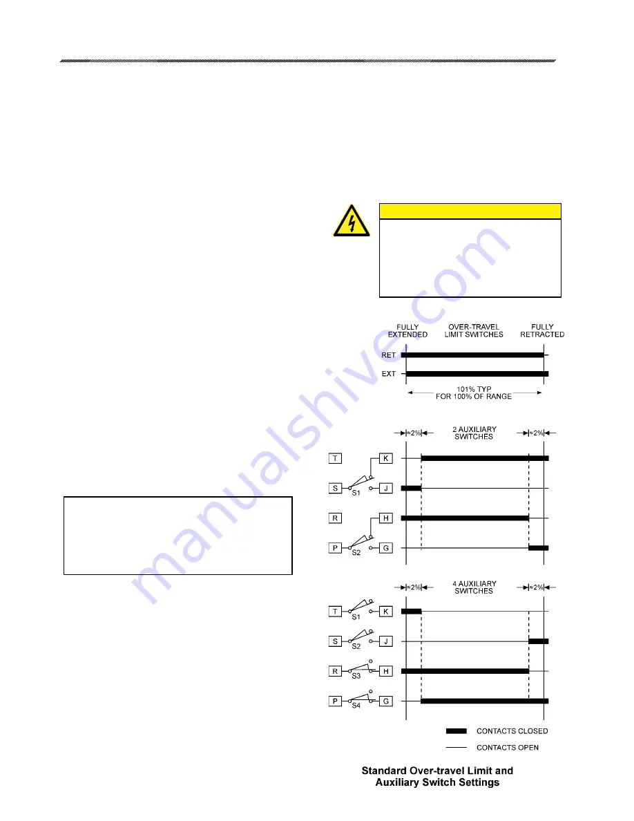
Switch Adjustments
All actuators are shipped with over-travel
limit switches factory-set for 101% of travel
unless otherwise specified at time of order. Limit
switches must be set inside the range of the built-in
mechanical stops to prevent stalling of the motor,
but can be reset to limit travel of the output shaft.
Optional auxiliary switches are set as shown below
unless otherwise specified at time of order.
Switches are operated by cams which are
clamped onto the control shaft. Setting a switch
involves loosening the cam, moving the actuator’s
output shaft to the desired position, and positioning
the cam so that it operates the switch at that point.
In the following procedure, the use of a continuity
meter is recommended to determine when the
switch opens or closes. If such a meter is not
available, it is possible to hear the switch click as
the contacts open and close.
CAUTION
Do not attach the meter or attempt
to move the switch cams until the
actuator is disconnected from the
line voltage and auxiliary switches
are disconnected from external
power sources.
Содержание 14-100
Страница 85: ...85 80 1403 01 Rev 3 17 18 2 1 6 5 8 6 3 4 9 14 15 25 7 16 CONTROL ASSEMBLY AND DRIVE TRAIN...
Страница 87: ...87 80 1403 01 Rev 3 14 15 17 18 2 1 6 5 8 6 3 4 9 14 15 25 7 16 CONTROL ASSEMBLY AND DRIVE TRAIN...
Страница 90: ...90 80 1403 01 Rev 3 NOTES...
Страница 91: ...91 80 1403 01 Rev 3...


