


33
C607215 - GB
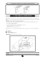
INSTRUCTIONS FOR FITTERS
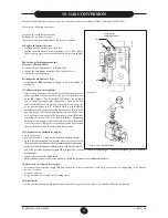
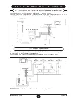
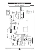
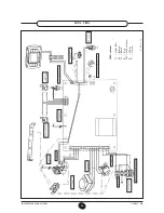
28. ELECTRICAL CONNECTION TO A ZONE SYSTEM
The contact for requesting the operation of the zones not controlled by the climate controller must be connected in parallel and connec-
ted to the terminals 1-2 “
Ta
” of the terminal block
M1
in figure 18.
The zone controlled by the climate controller is managed by the solenoid valve of zone 1, as illustrated in figure 18.
IMPORTANT:
ensure that the parameter
F04 = 2
(as in the factory setting - chapter 21).
Figure 18
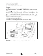
28.1 - CONNECTION OF THE RELAY bOARD (SUPPLIED AS ACCESSORY)
0812_1906 / C
G_1840
Figure 17
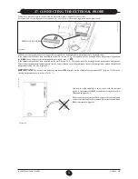
28.2 - ZONE CONNECTION
The relay board is not included in the standard boiler equipment and is supplied as an accessory.
Connect the connectors CN6 of the boiler electronic board and of the relay board by means of the FLAT cable provided. Connect the
terminals
1-2-3
of the connector CN1 to terminals
10-9-8
of the boiler terminal block
M2
(figure 17).
0802_2507 / C
G_1825
BOILER BOARD
RELAY bOARD ACCESSORY
ZONE 1
ZONE 1
(REMOTE CONTROL)
ZONE 2
(AMBIENT THERMOSTAT)
ZONE 3
(AMBIENT THERMOSTAT)
ZONE N
(AMBIENT THERMOSTAT)
SoLENoId VALVE
ZoNE 1
RELAY 2
RELAY 1


