


23
C607215 - GB
INSTRUCTIONS FOR FITTERS
The authorised Technical Assistance Service can convert this boiler to natural gas (
G. 20
) or liquid gas (
G.30, G. 31
).
Carry out the following operations:
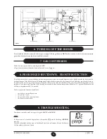
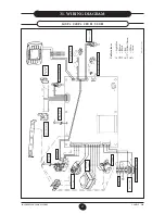
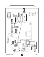
19. GAS CONVERSION
A) replace the main burner nozzles;
B) change the modulator voltage
C) new max. and min. calibration of the pressure regulator.
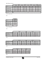
A) Replace the burner injectors
• carefully pull the main burner off its seat;
• replace the main burner injectors making sure to fully tighten
them to prevent gas leaks. Injector diameters are specified in table
2.
How to change the diaphragm nozzle
(for models 240i and 240 Fi)
• remove the gas supply pipe (1 in Figure 13b);
• change the diaphragm nozzle fitted on the gas valve (2);
• replace the gas supply pipe .
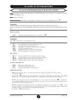
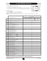
B) Change the modulator voltage
•
set parameter
F02
according to the gas used, as described in
section 21
.
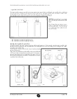
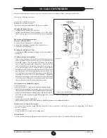
C) Calibrate the pressure regulator
• connect the positive pressure test point of a differential pressure
gauge (possibly water-operated) to the gas valve pressure test
point (
Pb
) (Figure 13a). For models 240 i/Fi use the pressure
tap (3) in the gas supply pipe (figure 13b). Only for models
with sealed chambers, connect the negative pressure test point
of the pressure gauge to a „
T
” fitting in order to join the boiler
adjustment outlet, the gas valve adjustment outlet (
Pc
) and the
pressure gauge. (The same measurement can be made by con-
necting the pressure gauge to the pressure test point (
Pb
) after
removing the front panel of the sealed chamber). Measuring
burner pressure using methods other than those described could
lead to incorrect results as the low pressure created by the fan in
the sealed chamber would not be taken into account.
C1) Adjustment to nominal heat output:
• open the gas tap;
• press
(section 3.2) and set the boiler on winter position;
• open a hot water tap that can provide a flow rate of at least 10
litres a minute or make sure there is maximum heat demand;
• make sure that the dynamic inlet pressure of the boiler, measu
-
red at the gas valve pressure test point (Pa) (Figure 13a) is correct (30 mbar for butane gas, 37 mbar for propane gas or 20 mbar for
methane gas ).
• remove the cover of the modulator;
• adjust the brass screw of the sleeve until you obtain the pressure values indicated in table 1
;
C2)Adjustment to reduced heat output:
• disconnect the modulator supply lead and slacken the red screw until you reach the pressure value corresponding to the reduced
power (see table 1);
• reconnect the wire;
• fit the modulator cover and seal the fixing screw.
C3) Final checks
• attach the additional plate supplied with the transformer specifying the type of gas and the calibration performed.
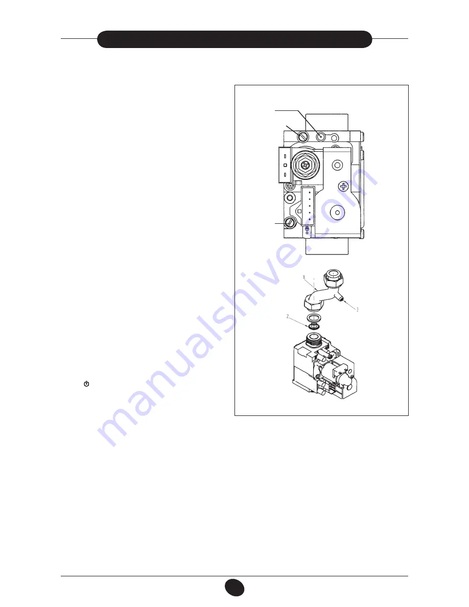
SIT Gas valve
SIGMA 845 model
Figure 13a
9912221500
Pc
Pb
Pa
0206_0501
Figure 13b (model 240i - 240 Fi)


