


15
C607215 - GB
INSTRUCTIONS FOR FITTERS
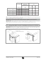
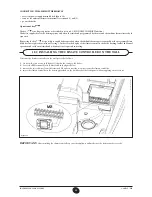
13. INSTALLING THE BOILER
After deciding the exact location of the boiler, fix the template to the wall.
Connect the system to the gas and water inlets present on the lower bar of the template. Fit two G3/4 taps (delivery and return) on the
central heating circuit; these taps make it possible to carry out important operations on the system without draining it completely. If
you are either installing the boiler on an existing system or replacing one, as well as the above, fit a settling tank under the boiler on the
system return line in order to collect any deposits and scale circulating in the system after flushing. After fixing the boiler to the template,
connect the flue and air ducts, supplied as accessories, as described in the following sections.
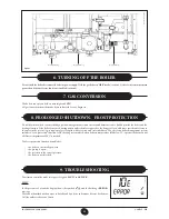
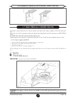
If installing the boiler with natural draught models
240 i - 280 i
make the connection to the flue using a metal pipe which, over time, will
resist normal mechanical stress, heat and the action of the combustion products and any condensate they form.
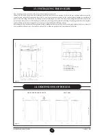
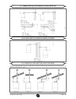
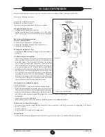
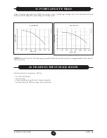
14. DIMENSIONS OF BOILER
971125_0201
Figura 4
1:
G 1/2 DHW outlet
2: G 1/2 cold domestic water inlet
3: G 3/4 heating return
4: G 3/4 heating delivery
5: G 3/4 gas inlet to boiler
020418_1000
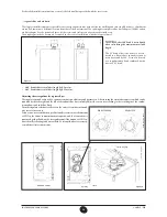
DISCHARGE AXIS WITH COAXIAL CURVE
Drill with a Ø 12 bit, fit the rawlplugs and the hooks provided
BOILER WIDTH 60
DHW
INLE
T
DHW
OU
TLE
T
HEA
TIN
G RE
TURN
HEA
TIN
G D
ELIVER
Y
GA
S INLE
T
FO
RCED
FL
OW
DISCH
AR
GE
AXIS
BO
ILER
HEI
GHT
950
Figure 5
0609_0504 / C
G_1848
140 Fi - 240 Fi - 280 Fi - 320 Fi
240 i - 280 i


