background image

BE1-79S General Information

1-5

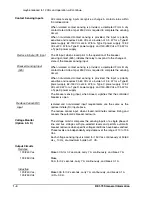
Reclosure Time Delay

Selectable from optional ranges of 0.1 to 2 seconds, 1 to 20 seconds
or 5 to 60 seconds.  Continuously adjustable with front panel control
over the selected range. Timing accuracy within 5%.

Reclose Signal

May be optionally specified to be continuous until breaker closes; or
for a maximum duration of 2 to 3 or 5 to 6 seconds.

Reset Time Delay

Continuously adjustable with front panel control over the range of 5 to
60 seconds.  Timing accuracy within 5%.

Voltage Monitor Range

Continuously adjustable over the range of 10 to 135 Vac.

Voltage Monitor Accuracy

Within 3% over the range of 0 to 150 Vac for a nominal input
frequency of 50/60 Hz, and at 25

!

C (or within 1% from 25

!

C over a

temperature range of 15

!

C to +40

!

C).

Maximum Trial Timer
Accuracy

Either 95 + 10.0 seconds (with Reset Timer B) or 15 + 2.0 seconds
(with Reset Timer C), for a nominal input frequency of 50/60 Hz at
25

!

C.  (Non adjustable.)

Temperature


Operating Temperature


Storage Temperature

-40

!

C (-40

!

F) to +70

!

C (+158

!

F).

-65

!

C (-85

!

F) to +100

!

C (+212

!

F).

Shock

In standard tests, the relay has withstood 15 g in each of three
mutually perpendicular planes without structural damage or
degradation of performance.

Vibration

In standard tests, the relay has withstood 2 g in each of three
mutually perpendicular planes, swept over the range of 10 to 500 Hz
for a total of six sweeps, 15 minutes each sweep, without structural
damage or degradation of performance.

Isolation

In accordance with IEC 255-5 and ANSI/IEEE C37.90, one minute
dielectric (high potential) tests as follows:

All circuits to ground:   

2121 Vdc

Input to output circuits: 

1500 Vac or 2121 Vdc

Surge Withstand Capability

Qualified to ANSI/IEEE C37.90-1978, C37.90a-1974, and IEC 255.

Weight

12.5 pounds net.

Case Size

S1 (double ended).

Содержание BE1-79S

Страница 1: ...INSTRUCTION MANUAL FOR SINGLE SHOT RECLOSING RELAY BE1 79S Publication Number 9 1410 00 990 Revision B 02 2001...

Страница 2: ...ould perform the procedures presented in this manual INTRODUCTION This Instruction Manual provides information concerning the operation and installation of BE1 79S Single Shot Reclosing Relay To accom...

Страница 3: ...tric Co Highland IL 62249 February 2001 It is not the intention of this manual to cover all details and variations in equipment nor does this manual provide data for every possible contingency regardi...

Страница 4: ...c 2 3 Reclose Timer 2 3 Reclose Fail Timer 2 3 Reset Timer 2 3 Voltage Monitor 2 4 Power Supply Output 2 7 SECTION 3 HUMAN MACHINE INTERFACE 3 1 Controls and Indicators 3 1 Switches 3 4 SECTION 4 INST...

Страница 5: ...ng closed for the reset interval Automatic reclosing of a tripped breaker requires that a reclose initiate signal RI be generated by the protective system and received by the reclosing relay prior to...

Страница 6: ...side the case assembly Upon receipt of a reclosing relay be sure to check relay style number against the requistion and packing list to see that they agree Style Number Example The Style Number Identi...

Страница 7: ...ble 1 1 Power Supplies Type Nominal Input Voltage Input Voltage Range Burden at Nominal B Mid Range 48 Vdc 24 to 150 Vdc 5 5 W C Mid Range 125 Vdc 120 Vac 24 to 150 Vdc 90 to 132 Vac 4 0 W 10 0 VA D L...

Страница 8: ...polarity sensitive and requires 24 60 Vdc at a burden of 3 5 W for a Type B power supply 62 150 Vdc at 4 5 W for a Type C power supply 12 32 Vdc at 2 0 W for a Type D power supply and 140 280 Vdc at...

Страница 9: ...uracy Either 95 10 0 seconds with Reset Timer B or 15 2 0 seconds with Reset Timer C for a nominal input frequency of 50 60 Hz at 25 C Non adjustable Temperature Operating Temperature Storage Temperat...

Страница 10: ...bus and dead line dead bus reclosing conditions The reclosing conditions voltage levels are established by adjustable controls on the front panel LB DB OV LL and DL OV The overvoltage limit OV mode a...

Страница 11: ...necessary Specific voltage ranges for the three new power supplies and a cross reference to the style number identifiers are shown in the following table Table 2 1 Wide Range Power Supply Voltage Rang...

Страница 12: ...s expired Option 3 2 or 3 3 RECLOSE FAIL TIMER Option 3 2 or 3 3 A RECLOSE FAIL signal is generated by the reclose fail timer if the reclose command from the relay does not cause the controlled breake...

Страница 13: ...ls for the line and bus inputs over the range of 10 to 135 volts This scheme establishes precise voltage conditions under which reclosing can occur Non selection of specific closing conditions prevent...

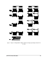
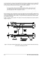
Страница 14: ...BE1 79S Functional Description 2 5 Figure 1 1 Figure 2 2 Voltage Monitor Conditions Modes and Voltage Levels Diagram Option 2 D or 2 S Only...

Страница 15: ...bus are provided by the dual function front panel controls DL OV and DB OV When the situation occurs in which both a live zone and a dead zone are elected and OV is selected for the live zone the dea...

Страница 16: ...relay is energized and its NC output contact is opened when power is applied to the relay Normal internal relay operating voltage maintains the power supply status output relay continuously energized...

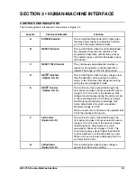
Страница 17: ...BE1 79S Human Machine Interface 3 3 Figure 3 1 Location of Controls and Indicators Figure 3 2 Optional Voltage Monitor Board CONDITION and MODE Switches Location...

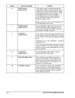
Страница 18: ...less than the overvoltage limit setting during the overvoltage limit mode E DB OV Control Option 2 S D This multi turn screw accessible through the front panel provides continuous selection over a ran...

Страница 19: ...This multi turn screw accessible through the front panel provides continuous selection over a range of 10 to 135 volts of the live line voltage monitoring level Adjustment is by small screwdriver Min...

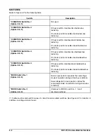
Страница 20: ...BE1 79S Human Machine Interface 3 3 Figure 3 1 Location of Controls and Indicators Figure 3 2 Optional Voltage Monitor Board CONDITION and MODE Switches Location...

Страница 21: ...on disables live line dead bus reclosing On down position enables live line dead bus reclosing CONDITION Switch No 5 Option 2 S D Off up position disables dead line dead bus reclosing On down position...

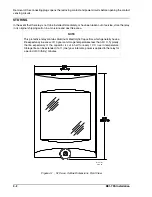
Страница 22: ...lay model and style number against the requisition and packing list to see that they agree MOUNTING The relay is intended to be vertically mounted in a location relatively free of moisture dust and ex...

Страница 23: ...torage life can be extended if at 1 one year intervals power is applied to the relay for a period of 30 thirty minutes 2 02 01 D1427 01 Removal of the connecting plugs opens the reclosing contact and...

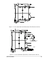
Страница 24: ...ETAIL A A SHOWING THE ADDITION OF WASHERS OVER THE BOSS TO TIGHTEN THE RELAY AGAINST THE PANEL CAS E Figure 4 2 S1 Case Double Ended Semi Flush Mounting Outline Dimensions Side View Figure 4 3 S1 Case...

Страница 25: ...4 4 BE1 79S Installation Figure 4 4 S1 Case Double Ended Projection Mount Outline Dimensions Rear View...

Страница 26: ...BE1 79S Installation 4 5 Figure 4 5 S1 Case Panel Drilling Diagram Semi Flush Mounting...

Страница 27: ...4 6 BE1 79S Installation Figure 4 6 S1 Case Double Ended Projection Mounting Panel Drilling Diagram Rear View Figure 4 7 Control Circuit Connections Typical...

Страница 28: ...BE1 79S Installation 4 7 Figure 4 8 Voltage Sensing Circuit Connections...

Страница 29: ...4 8 BE1 79S Installation Figure 4 9 RI RC and 52b Sensing Circuit Connections...

Страница 30: ...BE1 79S Installation 4 9 Figure 4 10 Internal Connection Diagram With Power Supply Status...

Страница 31: ...5 2 If equipped with Power Supply Status Output Option 2 F and with the unit in a powered up condition verify that the power supply status output contact is energized open terminals 11 and 16 Remove...

Страница 32: ...5 2 BE1 79S Operational Test Figure 5 1 Test Setup Diagram Typical Figure 5 2 Test Setup Diagram Voltage Monitor Option 2 S D...

Страница 33: ...ess to the voltage monitor board CONDITION and MODE switches remove the connecting plugs and remove the cradle assembly from the relay Step 15 Select the LL DB condition by setting CONDITION switch no...

Страница 34: ...50 and 150 milliseconds Step 29 About one minute after S2 was depressed LOCKOUT LED goes out and RESET LED lights Step 30 Set RECLOSE TIME fully clockwise 2 seconds to test maximum reclose time operat...

Страница 35: ...and RESET LED lights Step 46 Press and release S2 and immediately press S3 to simulate a breaker trip followed by an RC signal Step 47 Observe RESET LED goes out No automatic reclosure occurs Step 48...

Страница 36: ...ead line dead bus condition set CONDITION switch no 5 to the on down position Step 4 To select the overvoltage limit OV mode for the live line and or live bus conditions perform one or both of the fol...

Страница 37: ...tions until the associated indicator just lights To check the operation of the relay with the resulting set up perform the following steps Step 11 Momentarily press switch S1 to energize relay K1 Step...

Страница 38: ...operational check The procedures in Section 5 of this manual provide an adequate check to verify proper operation of the relay If the relay fails to function and factory repair is desired contact the...

Страница 39: ...Option 3 from 0 None to 0 No reclose fail timer continuous reclose output until breaker closes Added Option 2 D when Option 2 S is referred to in the manual Added new power supply information to Spec...

Отзывы: