BE1-79S Functional Description
2-1
SECTION 2 • FUNCTIONAL DESCRIPTION
GENERAL
The functional description contained in this section applies to the BE1-79S Single Shot Reclosing Relays
with all combinations of available options.
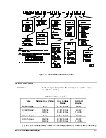
The reclosing relay, functionally shown in Figure 2-1, provides automatic reclosure of circuit breakers that
have been tripped by a protective relay. The relay uses a Form B auxiliary contact of the controlled circuit
breaker to detect the position of the breaker. A reclose initiate (RI) signal must be received from the
protective system prior to the closure of the breaker auxiliary contact. Closure of this contact indicates that
automatic reclosing is to be permitted.
A reclose cancel (RC) signal may be generated by the protective system. The RC signal must remain at
least 8 milliseconds before it is recognized by the relay. When RC is recognized, the relay is inhibited from
reclosing the controlled breaker. Following an RC signal, the controlled breaker must be closed by other
means. This permits the relay to be automatically reset by its internal reset timer as described below.
Contact sensing (52b, RI, and RC) is provided in one of two configurations. If isolated contact sensing
(Option 1-5) is specified, current is supplied to the contacts by the relay. If non-isolated contact sensing
(Option 1-4) is specified, direct current is supplied by the protective system through the contacts to the
polarity sensitive relay inputs. If the relay is equipped with the Type X power supply, these configurations
must be modified to accommodate an essential external sensing input module. (See Figure 4-9).
When Option 2-D or 2-S is included, a voltage monitor circuit compares the line and bus voltage levels
against pre-selected live-line/live-bus, live-line/dead-bus, dead-line/live-bus and dead-line/dead-bus
reclosing conditions. The reclosing conditions' voltage levels are established by adjustable controls on the
front panel. LB, DB/OV, LL and DL/OV. (The overvoltage limit (OV) mode allows an upper voltage limit to
be set for the recognition of a live-line or live-bus condition.) If the measured voltages are not correct for the
selected reclosing conditions, breaker closing is inhibited.
In some units (those with Reset Timer B or C) there is a Maximum Trial Timer on the voltage monitor board
that limits the opportunity for reclosing to either 95 or 15 seconds (for B and C respectively) after an open
breaker is sensed at the 52b input. If the required line and/or bus voltages have not been detected during
the specified time, the relay is inhibited from issuing a reclosing signal. The inhibit remains in effect until the
breaker is closed by other means, there-by circumventing the somewhat precarious situation that could
result from a relay poised to issue a reclose signal long after the instigating event has passed. (Like a loaded
gun with its safety off.)
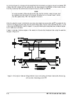
When the controlled breaker is closed, the reset timer begins to measure a programmed interval. If the
breaker remains closed for this interval, the relay resets and is ready to perform an automatic reclosing
operation following a subsequent breaker trip by the protective system. If the breaker opens before the
programmed interval has expired, the relay is disabled (locked out) and will not respond further to the
breaker position until it is reset. Resetting is accomplished by closing the breaker by other means and its
remaining closed for the duration of the reset interval.
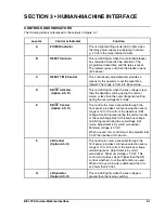
A red LOCKOUT indicator on the relay front panel lights when the relay generates the reclose command or
the breaker opens prior to expiration of the reset timer. It goes out when the reset time expires. A Form C
lockout relay is slaved to the LOCKOUT indicator and provides output contacts for monitoring the state of
the reclosing relay.
Содержание BE1-79S
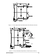
Страница 25: ...4 4 BE1 79S Installation Figure 4 4 S1 Case Double Ended Projection Mount Outline Dimensions Rear View...
Страница 26: ...BE1 79S Installation 4 5 Figure 4 5 S1 Case Panel Drilling Diagram Semi Flush Mounting...
Страница 28: ...BE1 79S Installation 4 7 Figure 4 8 Voltage Sensing Circuit Connections...
Страница 29: ...4 8 BE1 79S Installation Figure 4 9 RI RC and 52b Sensing Circuit Connections...
Страница 30: ...BE1 79S Installation 4 9 Figure 4 10 Internal Connection Diagram With Power Supply Status...


