


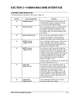


Locator
Control or Indicator
Function
3-2
BE1-79S Human-Machine Interface
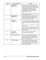
H
DL/OV Control
(Option 2-S, D)
This multi-turn screw, accessible through the
front panel, provides continuous selection over a
range of 10 to 135 volts of the dead-line voltage
monitoring level during the normal mode, or the
overvoltage limit for the live-line voltage
monitoring level during the overvoltage limit
mode. Adjustment is by small screwdriver.
Minimum voltage is CCW.
When unused, this control must be adjusted fully
CCW, then backed off one turn.
I
DL/OV Indicator
(Option 2-S, D)
This red LED lights when the line voltage is less
than the dead-line setting during the normal
mode, or less than the overvoltage limit setting
during the overvoltage limit mode.
J
LL Control
(Option 2-S, D)
This multi-turn screw, accessible through the front
panel, provides continuous selection over a range
of 10 to 135 volts of the live-line voltage monitoring
level.
Adjustment is by small screwdriver. Minimum
voltage is CCW.
This control must always be set higher than the DL
control, whether or not the LL function is used.
When not used, be sure (additionally) that it is set
lower than 80 Vac.
K
LL Indicator
(Option 2-S, D)
This red LED lights when the line voltage is
greater than the live-line setting.
L
RECLOSE TIME Control
This continuously adjustable dial provides a
means for the operator to set the reclose time
delay. The relay may be specified with one of
three optional ranges: 0.1 to 2 seconds, 1 to 20
seconds, or 5 to 60 seconds.
M
LOCKOUT Indicator
This red LED lights when the relay generates a
reclose command, or if the breaker reopens
before the reset timer has expired. The indicator
goes out when the breaker is closed and the
reset time interval expires.
Содержание BE1-79S
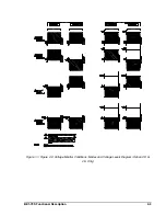
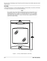
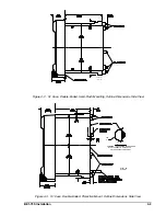
Страница 25: ...4 4 BE1 79S Installation Figure 4 4 S1 Case Double Ended Projection Mount Outline Dimensions Rear View...
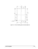
Страница 26: ...BE1 79S Installation 4 5 Figure 4 5 S1 Case Panel Drilling Diagram Semi Flush Mounting...
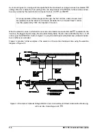
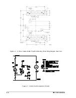
Страница 28: ...BE1 79S Installation 4 7 Figure 4 8 Voltage Sensing Circuit Connections...
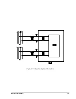
Страница 29: ...4 8 BE1 79S Installation Figure 4 9 RI RC and 52b Sensing Circuit Connections...
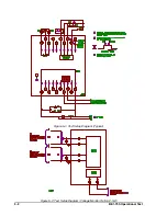
Страница 30: ...BE1 79S Installation 4 9 Figure 4 10 Internal Connection Diagram With Power Supply Status...