5-
7
BE1-79S Operational Test
NOTE
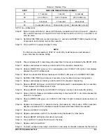
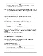
The voltage monitor is now set to allow reclosure when the line and bus voltage
conditions established in STEP 8 are encountered in the protective system.
NOTE
The voltage monitor is now set to inhibit reclosure when the line and/or bus conditions
established in STEP 9 are encountered in the protective system.
NOTE
Steps 16 through 20 provide a means of calibrating the Maximum Trial timer . This timer
is only present when Reset Timer Option B or C is installed. For all other relays the
operational test is concluded .
NOTE
The voltage monitor is now verified to operate in accordance with the previous
selections.
the DB/OV indicator just lights.
Step 9. If OV was selected (STEP 4) adjust the T1 (bus) and/or T2 (line) output voltages to the desired
higher voltage limit such that, for anticipated voltages above the setting(s), reclosure will not
occur.
Step 10. Slowly adjust the OV voltage level adjustments that correspond with the selected conditions until
the associated indicator just lights.
To check the operation of the relay with the resulting set-up, perform the following steps:
Step 11. Momentarily press switch S1 to energize relay K1.
Step 12. Close switch S4 to supply RI signal to relay.
Step 13. Adjust the T1 (bus) and T2 (line) outputs to within reclosure enable zones established in the
previous steps.
Step 14. Press and release switch S2. Relay K1 should momentarily trip, then reset.
Step 15. If the OV mode was selected, adjust the appropriate input voltage (T1 or T2) until the voltage
exceeds the OV level. With relay K1 energized, press and release switch S2. Relay K1 should trip,
but no reclosure should occur.
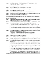
Step 16. Set Condition Switches 1 and 2 down, 3 through 5 up .
Step 17. Set Mode Switches 1 down, 2 up .
Step 18. Place a voltmeter between pin 39 of Voltage Monitor board and ground. (Should read 0 volts. )
Step 19. Apply a high (tripping) signal to relay terminal 14 (52b) and note the time it takes until terminal 39
goes high . Time should be as follows.
For Reset Option B: 95 +10 seconds
For Reset Option C: 15 +2 seconds
Step 20. If time period falls outside of the specified tolerance, adjust potentiometer R60 as required .
Содержание BE1-79S
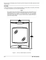
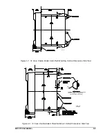
Страница 25: ...4 4 BE1 79S Installation Figure 4 4 S1 Case Double Ended Projection Mount Outline Dimensions Rear View...
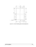
Страница 26: ...BE1 79S Installation 4 5 Figure 4 5 S1 Case Panel Drilling Diagram Semi Flush Mounting...
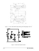
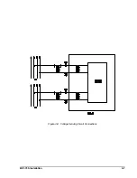
Страница 28: ...BE1 79S Installation 4 7 Figure 4 8 Voltage Sensing Circuit Connections...
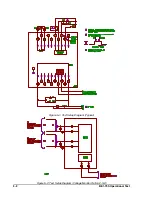
Страница 29: ...4 8 BE1 79S Installation Figure 4 9 RI RC and 52b Sensing Circuit Connections...
Страница 30: ...BE1 79S Installation 4 9 Figure 4 10 Internal Connection Diagram With Power Supply Status...

