BE1-40Q General Information
1-1
SECTION 1 • GENERAL INFORMATION
APPLICATION
General
Loss of excitation protection is applied on nearly all synchronous generators. Reduced or complete loss of
excitation can cause loss of synchronism, instability and, possibly, damage to the generator from
overheating. Many modern excitation systems include minimum-excitation limiters to prevent
underexcitation; however, loss of excitation protective relays are still applied as backup to these automatic
controls. BE1-40Q Loss of Excitation Relays provide this protection by monitoring the field excitation
(measuring the magnitude and direction of var flow) and tripping the generator before serious damage to
the generator can occur.
Synchronous generators in parallel are normally operated in the overexcited (lagging) region which allows
generation of reactive power (vars). Although the field excitation may be safely adjusted to cause the
generator to absorb vars (leading), this is usually avoided because stability is unreliable under this condition.
When field excitation is not sufficient to maintain the terminal voltage of an interconnected generator, the
system will attempt to supply reactive power to excite the generator. If the system cannot supply the
required vars, the weakened field may allow the rotor to slip poles during disturbances such as load changes
or faults, causing loss of synchronism.
When the system can supply the necessary vars, the generator will act as an induction generator, drawing
excitation from the system. The machine voltage will remain above the setting of undervoltage relays, but
the current induced by the rotor slip will flow in the damper (amortisseur) windings. The excessive heating
caused by the current flow reduces machine life exponentially.
Under either condition, BE1-40Q Relays will detect the increased vars at the generator terminals as a loss
of excitation and trips the generator to prevent loss of synchronism or excessive heating within the
generator.
Capability Curves
Generator manufacturers supply capability curves that specify the operating limits of a particular machine
(similar to those shown in Figure 1-1). The curves are derived from the heating characteristics that occur
on the stator end iron, the stator winding, and the rotor winding. Plotted on the complex power plane, real
power P (kW) is on the horizontal axis and reactive power Q (var) is on the vertical axis.
An additional limit is often included on these curves, as shown in Figure 1-2. Here, the steady state stability
limit further defines the safe operating limit of the generator. If the stability limit is exceeded, an out-of-step
condition can occur due to loss of synchronism.
BE1-40Q Operating Characteristics
BE1-40Q relay characteristics closely follow the generator capability curves. The response characteristic
is represented by a line eight degrees from horizontal, placed above the most restrictive limit of normal
operation. As shown in Figure 1-3, the attendant intercept of the line on the Q axis (at -0.4 per unit vars in
this example) is used to establish the pickup of the relay. A front panel rotary switch is used to set the TAP
setting. Refer to
Section 5, Setting And Testing for specific information on determining the pickup setting.
Содержание BE1-40Q
Страница 13: ...2 2 BE1 40Q Human Machine Interface Figure 2 1 Location of Controls and Indicators ...
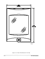
Страница 19: ...4 2 BE1 40Q Installation 2 02 01 D1427 01 Figure 4 1 S1 Case Outline Dimensions Front View ...
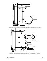
Страница 22: ...BE1 40Q Installation 4 5 Figure 4 6 S1 Case Outline Dimensions Rear View ...
Страница 25: ...4 8 BE1 40Q Installation Figure 4 10 Sensing Input Connections Figure 4 11 Output Connections ...
Страница 35: ...5 8 BE1 40Q Setting and Testing Figure 5 4 Blank Graph ...


