


3-2
BE1-40Q Functional Description
Front Panel Pickup Setting
!
V
AB
(I
B
)
3
sin(8
!
"
!
)
cos8
!
(3.1)
I
B
!
Front Panel Pickup Setting
V
AB
3cos8
!
sin(8
!
"
!
)
(3.2)
Figure 3-2. Phase Shift Example
The response of the relay is:
or
Where:
V
AB
= phase A to phase B voltage magnitude
I
B
= phase B current magnitude
!
= system power factor angle = (voltage angle) - (current angle)
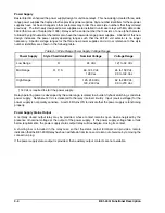
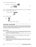
Current Sensing
The monitored current is derived from the secondary of a system current transformer rated nominal five
amperes. An internal current transformer (CT) provides isolation and scaling for proper relay operation. The
front panel HI/LOW RANGE Switch uses the tapped secondary of the internal CT for range selection to
increase pickup stability.
Note that when the connection plugs (paddles) are removed, the CT inputs are shorted.
HI/LOW RANGE Switch
The front panel HI/LOW RANGE switch selects which secondary winding of the internal CT is connected to
the TAP Switch and thus the measurement circuitry. The position of this switch may be changed while
sensing current is present. The effect of this switch, in conjunction with the TAP switch, is shown in the
Содержание BE1-40Q
Страница 13: ...2 2 BE1 40Q Human Machine Interface Figure 2 1 Location of Controls and Indicators ...
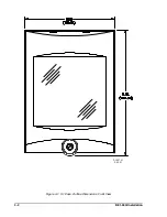
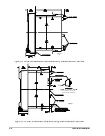
Страница 19: ...4 2 BE1 40Q Installation 2 02 01 D1427 01 Figure 4 1 S1 Case Outline Dimensions Front View ...
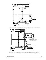
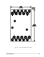
Страница 22: ...BE1 40Q Installation 4 5 Figure 4 6 S1 Case Outline Dimensions Rear View ...
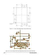
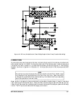
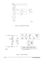
Страница 25: ...4 8 BE1 40Q Installation Figure 4 10 Sensing Input Connections Figure 4 11 Output Connections ...
Страница 35: ...5 8 BE1 40Q Setting and Testing Figure 5 4 Blank Graph ...


